
Learn From My Mistake In Using Sunwa Analogue Multimeter

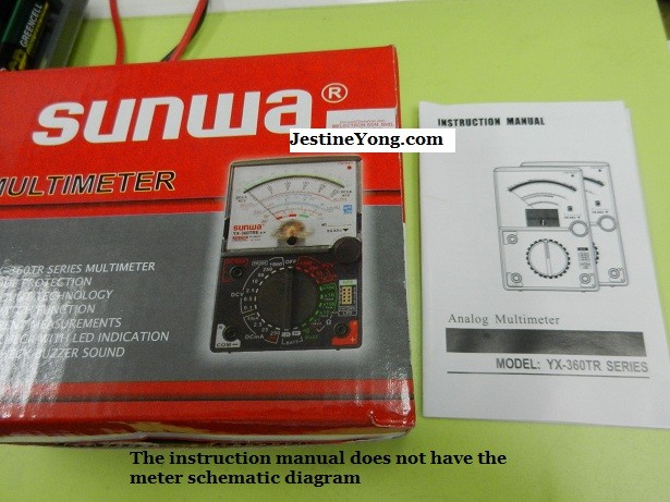
There is no doubt that the Sunwa Analogue meter is one of my favorite meters in electronics troubleshooting. I have used this meter since the early days (mid of 80’s) I ventured into electronics repair. So many types of electronic components it can check and I just can’t do the repair work without it. It already helped me in so many repair jobs and the meter already paid itself back thousands of times!
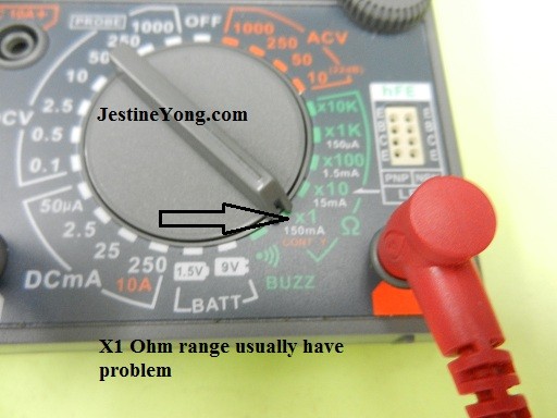
Recently there was a customer sent in a laser printer for repair and the complaint was no power. I found that that main fuse was good so I disassembled the circuit board from the casing. I checked on the big filter capacitor and made sure there was no voltage so that I can begin to work on the board. The voltage reading of the capacitor was zero volts and this means I can start to check on the component. The moment I placed my test probes (set to x 1 Ohm) on the power FET pins (to check if FET is shorted or not) I could hear a loud sound “Poof” from my new Sunwa analogue meter.

I experienced this before in the old Sunwa meter model. I knew that the internal resistor of the meter could have blown and the cause of the problem usually was due to the un-discharged voltage in the main big filter capacitor. But I had checked earlier that there were zero volts across the main filter capacitor. Later I realized that one of my meter probes actually had an intermittent loose connection. It did not insert properly into the connector. This is my mistake and I should have check the test probes first before performing any repair work.

This is the reason why I got zero volt when measuring the voltage across the main filter capacitor. After connecting back the probe and rechecked the main filter capacitor (set to 1000VDC) it was showing about 300VDC wow! This also proven that the laser printer itself already have problem. Due to the intermittent loose connection in one of the test probes, my new meter was blown.
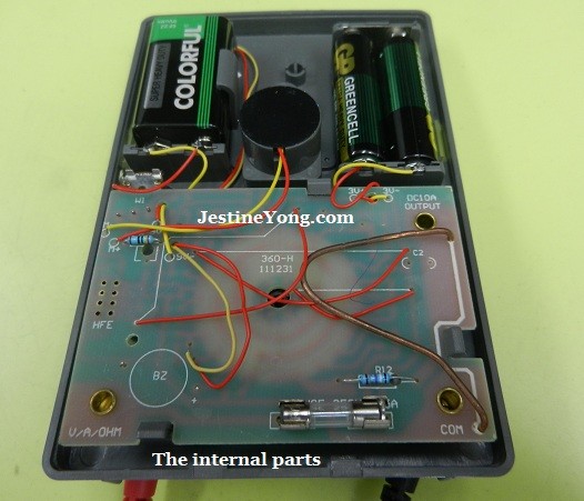
Well, as a repairer I have to open up the meter and start to repair it. Since this is a newest Sunwa analogue meter thus many SMD resistors were used in the circuit board.

Upon close inspection in the X1 Ohm range area I saw 2 SMD resistors with the value of 36R5, one of them already had a burnt mark. Both resistors tested open circuit. There were another one SMD resistor with a coding of 2000 (200 Ohms) also had an open circuit. It was replaced with a 220 Ohm SMD resistor.
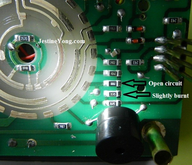
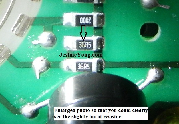
I don’t have info for this SMD resistor code 36R5. The question now is how to read this SMD code? Here is the tip, when I checked on other good SMD resistors in the meter circuit board I found that 10R0 was 10 Ohm, 7R87 was 7.8 Ohm so this 36R5 should be 36 Ohm. I don’t have the info for “5” (36R5) or even “7” (7R87) at the end of the resistor.
Note: If you have the info please do leave a comment at the end of this article-thanks.
Since these two identical SMD resistors was connected parallel in the circuit this means the total value is 18 ohm based on the resistor parallel formula.
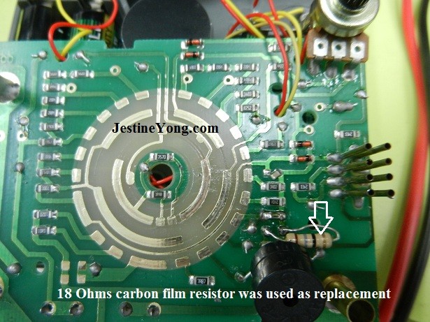
If you owned the older model of Sunwa 360 TRe analogue multimeter I believe you have replaced the X1 Ohm resistor before and the value was also 18 Ohm. Why X1 Ohm resistor value? Because this is the most frequent range that we use to perform checking and troubleshooting. This is why the failure rate is high on the X 1 Ohm range.
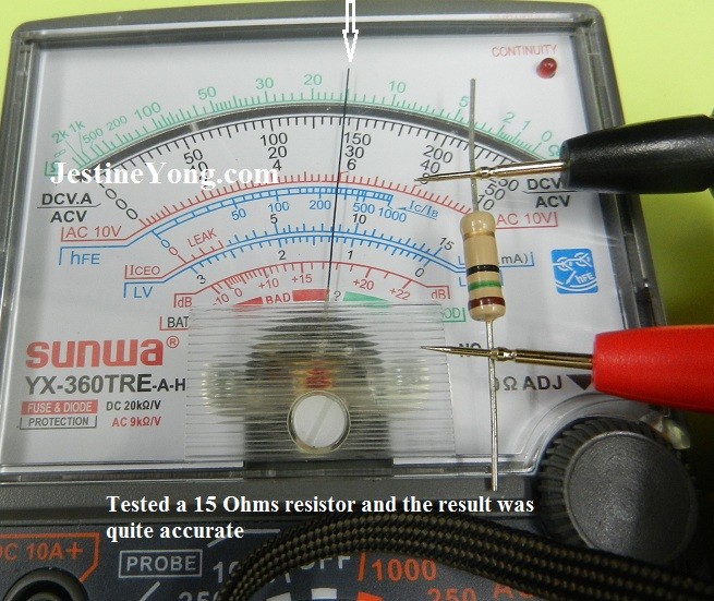
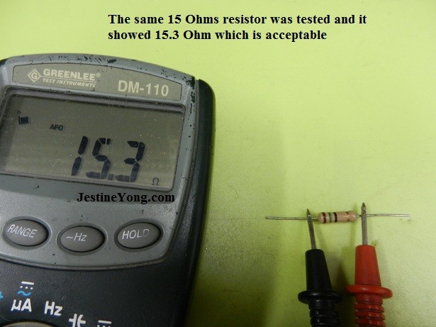
Since I don’t have the parts for the SMD resistor so I used carbon film ½ watt 18 Ohm as replacement. If I have 1/8 watt or 1/4 watt I will definitely use it. After I have soldered the resistor, I performed the value test to see if it still produces accurate reading or not. Check out the photo below:
Conclusion- If you own this type of meter and if the X1 Ohm internal resistor have problem you can always use 18 Ohm carbon film resistor as replacement. In the future if you came across SMD resistors coding that you don’t understand, always refer to the surrounding SMD resistors coding for answer. One more thing, always make sure the test probes are connected properly to avoid any future problem to the meter. My mistake can be your gain.
By the way if you want to learn how to use multimeter to perform troubleshooting in electronics circuit you can check out my Ebook HERE for more information.
You may also interested in this article too “10 Reasons How You Can Increase Your Electronics Repair Rate”
Thanks
JestineYong

 (125)Dislikes(0)
 (17)Dislikes
 (1)
(1)
42 Comments
Leave a Reply
Cancel reply


DESMOND
August 10, 2015 at 2:26 pm
Hi Jestine,
I have a Honeytek digital multi-meter DT9205A+ and am looking for a schematic diagram / service manual
to do a repair on my multi-meter.
Somehow the ac 750 volt range got too much voltage. The meter did not blow any fuses, but all other function are giving the wrong readings.
Regards
Desmond
Jestine Yong
August 10, 2015 at 8:35 pm
HI Desmond,
Sorry I do not have this schematic. Try trace from the AC750Vac selector circuit track to find if there is any component that have problem.
Jestine
Choong
January 14, 2016 at 12:53 am
36R5 = 36.5 ohm
7R87 = 7.87 ohm
Source:
http://www.hobby-hour.com/electronics/4-digit-smd-resistors.php
uditha
January 15, 2016 at 11:20 pm
what is value for 2000 on smd resistor?
Jestine Yong
January 19, 2016 at 8:48 pm
HI Uditha,
Is 200 Ohm. Check out the value in the below link:
http://www.hobby-hour.com/electronics/4-digit-smd-resistors.php
Jestine
John Lind
December 9, 2016 at 8:54 pm
Jestine . . . your experience is exactly why I do NOT use Rx1 range for continuity checks with analog meters (most DMM have a continuity setting). I use the Rx10 range, sometimes higher. Some meter manuals and instructors will tell you to do this to provide some minimal protection. I just repaired a GriefKit IM-105 (aka Weston 660) that I built nearly 40 years ago that had been gathering dust since I loaned it to a dude 30 years ago. He did the typical boneheaded Rx1 range continuity check on a circuit that had power. Blew out the 1/2 Watt 19.5 ohm 1% precision reference resistor used as the voltage divider in all resistance ranges (the Rx1 resistor you talk about). Had to replace it with two 39 ohm 1% in parallel. Getting special value resistors, not to mention high precision ones, to replace those used for a multimeter's resistance ranges is nearly impossible. It's working now and I will NEVER loan out an analog meter again. You could have measured the identical one you pulled along with it. I suspect it's a precision resistor with an odd value and would have pursued finding its exact value in replacing them with nothing less than 1% resistors. If it's the Rx1 resistor, it's the reference for all the resistance ranges making its precision the most critical. Most of the resistors inside these multimeters are precision, typically 1%, occasionally 0.5% or better in some of the high precision meters. Custom precision resistors with odd values are commonplace, and replacing them can involve some ingenuity putting what's available in series and/or parallel. I may replace a second resistor (the Rx10) as it may have been damaged. Still testing the meter with some high precision resistors with 180-220 Ohm values (mid-scale).
Jestine Yong
December 10, 2016 at 10:16 pm
Hi John,
Thanks for the explanation.
Jestine
Mina
March 18, 2017 at 10:44 pm
hello
i have a problem with my dt9205a
display -1 all time and i don't know what i do to fix this problem please help me
Jestine Yong
March 24, 2017 at 4:24 pm
Hi Mina,
I do not own this meter thus I do not have the exact answer for you. You need to open it up and check for any dry joints, bad connections/contact, bad components especially tracing from the positive probe.
Jestine
rafael
July 8, 2017 at 4:01 pm
Ive experience ceramix cap damage inside my multimeter. Its value is 473. But when i replace it with same value, the nedle become wild over to the right. Even though i try to turn the adjust variable resistor, it seem doesnt make any effect at all.
Jestine Yong
July 9, 2017 at 8:57 pm
Hi Rafael,
I suggest that you check the components that is related to the ceramic capacitor.
Jestine
Maher Alsayid
August 22, 2017 at 3:52 pm
Hi, im using Sunwa YX-360TRE , im new on using multimeter im trying to see the Amps of a 10amps 12v stepdown converter for a project and i want to adjust the 10amps to 4.7amps .
there is 0 to 250 / 0 to 50 / 0 to 10 . i changed the red line to DC 10A+ and the multimeter to 250 and the reading was 90 on the first line thats 0 to 250.
what should i do to solve my problem because i dont know what is the reading is it 90ma or 9A or 19 or 3.80 if i follow (0 to 250 / 0 to 50 / 0 to 10) .
thank you very much.
Jestine Yong
August 23, 2017 at 7:07 pm
Hi Maher,
This model of meter does not have DC10 Amp. It has DC10 Volt. Can you send to me a photo of how you get the DC10A + ?
Jestine
Maher Alsayid
August 27, 2017 at 6:28 pm
thank you for your reply,
https://www.jestineyong.com/wp-content/uploads/2013/11/analogsunwameter15ohm.jpg
its the same Multimeter that you have in the post.
the DC10A+ is above the COM, as i explained in the earlier comment that i plugged the red wire in the DC10A+ and set the Multimeter to 250 as in the picture
https://www.jestineyong.com/wp-content/uploads/2013/11/sunwaanalogneterx1ohm.jpg
and the Multimeter show the reading(90) if we looked from 0 to 250 in the DCVA as in this picture
https://www.jestineyong.com/wp-content/uploads/2013/11/analogsunwameter15ohm.jpg
my question is what is ( 90 ).
thank you very much
Jestine Yong
August 29, 2017 at 9:31 pm
Hi Maher,
I did not noticed it. That is a DC 10 amp. This means it used to measure DC ampere. What did you measure when you said it got 90?
Jestine
Maher Alsayid
August 31, 2017 at 1:18 am
Hi,
Im measuring and output of a stepdown converter, same is in the link
https://images-na.ssl-images-amazon.com/images/I/51En833BfuL._SY355_.jpg
i want to use it for led that need 4.2amps .
the step down converter is 10A 35v that i have.
when i tested the result it show 90 on the range 0 to 250.
i set the multimeter to apms 250 the one in this link under the arrow
https://www.jestineyong.com/wp-content/uploads/2013/11/sunwaanalogneterx1ohm.jpg
thank
Jestine Yong
September 2, 2017 at 1:13 pm
Hi Maher,
If you set to the 250 (10amp) under the DCmA range and it showed 90 which could also mean 3.8 amp if you look at the 10 ACV scale. How did connect the probes to measure the current?
Jestine
Maher Alsayid
September 3, 2017 at 1:05 am
Hi,
i connected them to the output of the stepdown converter without a load,
i thought that AC is for the electricity as 220v or 120v .
thank you for your help appreciate it so much.
i want to power a 30pc led UV 405nm 700ma that require 4.2Amps, i connected them on series and parallel for an lcd 3D printer.
thank you again.
Jestine Yong
September 7, 2017 at 4:39 pm
Hi Maher,
First thing first, connect the AC power to a power supply and from the power supply you connect it to the step down converter. And from the step down converter you connect it to the 30 pcs of LED. Let say if the 30pcs LED use 27 volt and 4.2 amps then what you need to do is to adjust the step down converter to 27 volt. You do not need to measure the current because the step down converter is a 10 amp converter and it can support the 4.2 amp LEDs. If you want to measure the current draw then I suggest that you google for " how to connect ammeter in series". From there you would know what is the exact amp draw from the 30 LEDs.
Jestine
Jestine
Robert Calk
September 27, 2017 at 9:06 am
Hi Mr. Yong,
Are you sure that meter is not a fake Sunwa meter? It looks like a really cheap build, and the quality does not even compare to my BK Precision 114A. The difference in quality between them is like night and day.
Jestine Yong
September 27, 2017 at 10:59 am
Hi Robert,
Original Sanwa meter did not have this kind of design. This Sunwa meter of moderate quality and found it to be good and not too expensive. The most important thing that this meter has is the x 10 K ohm range. Bk Precision meter is made in USA so it will have the quality.
Jestine
Robert Calk
September 28, 2017 at 1:51 am
My main concern is that using that meter for too much voltage/current could be dangerous.
Jestine Yong
September 28, 2017 at 8:01 am
HI Robert,
According to the manual the max voltage is 1000 volt and ampere is 10 amp. Just don't exceed the rating and it will be fine.
Jestine
Robert Calk
October 3, 2017 at 1:46 am
It's plain to see that those meters are not designed to take that much current/ voltage, and to recommend them is grossly irresponsible. And the manufacturers should be criminally prosecuted.
Jestine Yong
October 3, 2017 at 9:10 am
HI Robert,
For your information, I have been using this kind of meter since in the 80's (older model). Just use it within the spec of the meter. If it says 10 AMP is max then do not exceed the rating. Furthermore there is a built in fuse also. Even if you are using a branded meter that is rated as 10 amp and you check on a 20 amp point or line, the meter would still blow up. Just use the meter within the spec allowed and it will be fine.
Jestine
Robert Calk
October 4, 2017 at 2:25 am
I do not believe that meter will handle 10A safely. I wouldn't even trust my BK 114A to handle that much current, or 1KV for that matter. It's not only the meter they should worry about but also the cheap probes. There's one guy on Youtube where the cheap probe blew up in his hand.
I would recommend poor people to save their money and buy a used Fluke on eBay. They can get used Flukes at a decent price now-a-days. I'm just a firm believer that safety should be our first concern.
Farshid
November 20, 2017 at 5:47 am
Hi,I want a service manual or image of smd resistor of sunwa analog multimeter model ks_268 because two smd resistor are burn ,can you help me?
Jestine Yong
November 23, 2017 at 8:03 am
Hi Farshid,
Sorry I do not have such model of meter.
Jestine
dalganjan kurre
February 1, 2018 at 10:25 am
how to test with multimeter of sunwa analog multimeter volt /kohm sensityvity
George
September 22, 2018 at 9:10 am
Hi Jestine,
I have a YX-360 TR e-b, Analog Multi meter.The continuity LED light does not light up when testing the continuity; but the buzzer sounds as well as the gauge reads. What could be the problem and how to rectify the same.
Thanks.
Jestine Yong
September 25, 2018 at 8:09 am
Hi George,
You need to open it up and check the LED and if it is good you need to trace from the LED leads to see if there is any broken track or open resistor.
Jestine
Ryan F
November 10, 2018 at 10:26 pm
Hi Jestine
I have a digital+analog 82320 craftsman multimeter.
No matter what setting i put it to it shows a small value not even connected to anything.example if i put it to vdc and probes seperated and not connected to anything it will be around 1.7 vdc. Even touching probes together under continuity it shows resistance value..
Any thoughts? Possibly burnt some resistors??
Jestine Yong
November 12, 2018 at 8:21 pm
Hi Ryan,
For many digital multimeters, setting on the DC mode will show some mV which is negligible. But 1.7 Volt would be too high. Have you tried check a 1.5 volt battery source to see if the result is 1.5 volt or 3.2 volt? As for the continuity, most low cost probes will have higher resistance as compare to good probes. A good probe should show less than 1 Ohm of resistance and the reading is stable. A bad quality probe will show higher resistance (few ohms) and the reading will fluctuate.
Jestine
Muhammed azhar
May 19, 2019 at 11:23 pm
Sir,my yx3600 multymeter smd resistor was burned.I dont know its specification.its totally burned. Can you pls send its circuit diagramme.
Jestine Yong
May 20, 2019 at 10:31 am
Hi Muhammed,
Sorry I do not have the circuit diagram.
Jestine
Faisal
July 20, 2019 at 3:49 am
Hi
I'am trying to know how can the board work inside YX-360TRD in details to measures AC,DC voltage or resistance .Do you have any idea ?
Jestine Yong
July 20, 2019 at 9:06 pm
Hi Faisal,
There was no information about how the internal circuit board works.
Jestine
Babul Akter
October 7, 2019 at 6:13 pm
My PROFACE touch screen display hang (touch not response) some .power off/on then some times work other wise long time hang. then power/on off.then work ambien temperature 40 degree centigrade.
DEHONG TANG
August 4, 2022 at 7:23 am
I have the same meter. R8 on that board is burnt out. Do you know the number of this resist? Thanks.
Jestine Yong
August 9, 2022 at 10:40 am
Hi Dehong,
My meter does not have the board marking. Could you take photo of your meter and mark the R8 location and send to my email? You can go to Contact us page to send message to me. From there I can compare the value and let you know. I was wondering how come your meter have board marking and mine does not have when you said you have the same meter? I'm curious and need to look at your meter photo.
Thanks
Jestine
Dima
January 2, 2023 at 2:00 am
Hello Jestine Yong
My Name is Dima recently purchased this device and very happy. 50 volt scale shows now perfect changing 750 K resistor Good Luck! Love And Light! Here is the image.
Jestine Yong
January 2, 2023 at 7:59 am
Hi Dima,
Thanks.
Jestine