
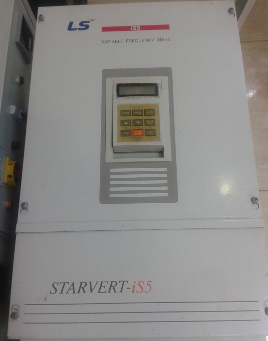
Modification Of Transistor/Resistors In AC 37KW LS Inverter
Last week a customer brought to my shop an ac inverter of 37 KW in an urgent situation (the main drive in one of his production lines), as he described the problem , there was no torque in the motor , it rotates but you can stop it by hand.
I made my first visual check but there was no sign of burns or defected component s, I start making Multimeter checking on the critical components such as the IGBT , Capacitors and etc but no problem seem to be there.
I start digging in the SMD components around the triggering circuit , when I came to the Q27 and with comparing to his counterparts , I notice some different reading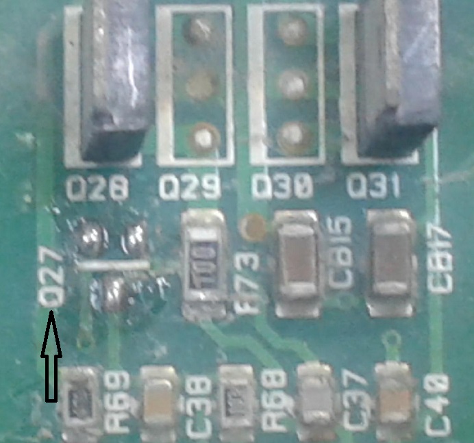
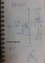
So I checked the datasheet of the SMD transistor (NA), it was a normal transistor but with 2 (4.7KOhm) for self biasing ,as the situation urgent and I can’t wait for two weeks for the new transistor to arrive. I had to come out with a solution fast.
I made my decision to build one (it looks strange)but I made it as shown in the photos:
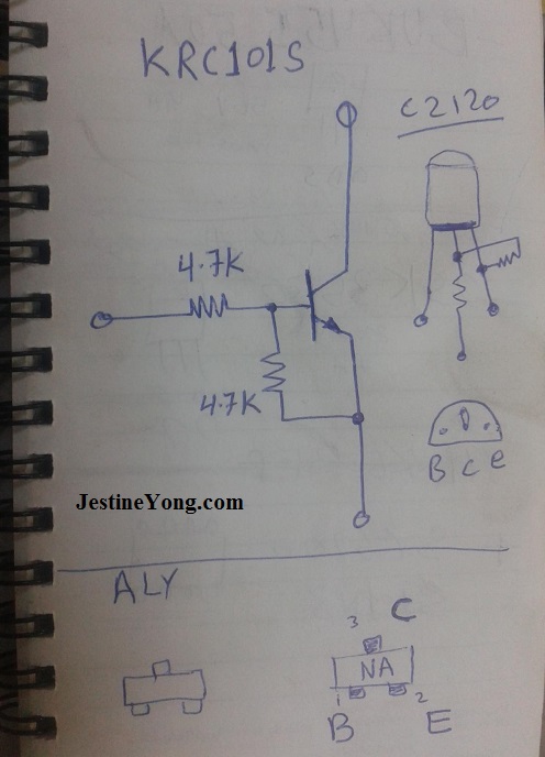
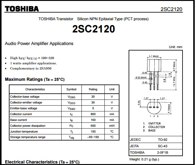
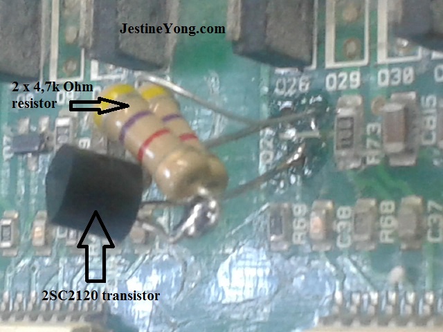
I used transistor 2SC2120 with 2 resistor 4.7kohm, then the inverter was installed in the machine and works fine and the important thing is my customer was so happy.

This article was prepared for you by Muftah H Shawish from Misrata Libya. He has more than 25 years experience in troubleshooting and repairing of industrial systems, electronic control system, temperature controller, motors drives and automotive control unit. He was a BET graduate, currently work as a manager of electrical repair dept in Libyan steel company and also run his own electronics repair shop.
Please give a support by clicking on the social buttons below. Your feedback on the post is welcome. Please leave it in the comments.
P.S- If you enjoyed reading this, click here to subscribe to my blog (free subscription). That way, you’ll never miss a post. You can also forward this website link to your friends and colleagues-thanks!
 (176)Dislikes
 (0)
(0)
32 Comments
Leave a Reply
Cancel reply


Robert Calk
October 21, 2015 at 9:15 am
Good job, Muftah - nice improvising. Hopefully it won't vibrate loose and short out the PCB.
Muftah
October 21, 2015 at 2:37 pm
Thanks Robert, regarding the vibration , i tried to fix them with Silicone , hopefully will do the job>
rauljose go
October 21, 2015 at 9:26 am
muftah shawish good day to you all... very impressive repair of such industrial inverter. i wish am also could experience that kind of equipment in the near future.i really like that much repair, by the way im 63. how i wish to consult to you regarding big inverter test and repair. many thanks to you all and in gratitude to mr. jestine yong.
Muftah
October 21, 2015 at 2:44 pm
Hi Rauljose,
i also like repairing industrial units and systems , such as inverters , plc (input and out puts cards),, etc and i will be happy to help you and exchange knowledge with you, please feel free to contact me for any technical issue .
Paul
October 21, 2015 at 10:24 am
Great repair, I am interested to know if you compared the characteristics' of the 2 transistors and what made you select the 2SC2120? Is it that by "normal" the SMD transistor was a standard type with characteristics similar to a BC108 or BC109?
PaulS
Muftah
October 21, 2015 at 2:49 pm
Hi Paul, the smd NA was normal transistor except it has these 2 resistor for biasing (just for space reason), i have just take care of volt and current and pin configuration and everything went ok ..
sagar sen
October 21, 2015 at 11:49 am
sir, u just inspire me to take some risk.. Thank u very much
Muftah
October 21, 2015 at 2:50 pm
Thanks Sagar for your words.
Robert Calk
October 21, 2015 at 6:24 pm
Hi Sagar,
It really isn't that much of a risk. Just go to the datasheets and choose a transistor, or whatever, with similar characteristics like Mr. Muftah did. I didn't have time to check those datasheets myself last night, but I'm sure that he did before he chose that transistor.
Just remember the rule of electronix: When in doubt, check the Datasheets.
Diaa fawzey
October 21, 2015 at 2:23 pm
It's really an interesting and courage repair.
thank you MR Muftah.
and thank you very much Mr jestine.
Muftah
October 21, 2015 at 4:50 pm
Thanks Diaa fawzey for your comment.
Albert van Bemmelen
October 21, 2015 at 5:43 pm
Hi Mr Muftah, good job! The different readings were obviously taken with Q27 (SMD code NA) measured out of the circuit. As you probably didn't have any information about the Inverter itself when measuring any voltages in-circuit?
I found your Transistor with code NA twice on http://www.s-manuals.com/pdf/datasheet/k/r/krc101s-krc106s_kexin.pdf
AND also as another NPN without any resistors at:
http://www.s-manuals.com/pdf/datasheet/f/m/fmmta05%2C_fmmta06_zetex.pdf
But you selected the one transistor with the resistors probably because you measured those resistors in the defect SMD with NA code?
And I gues you didn't have 4.7Kohm SMD resistors either. Using those would probably have been wiser because of the mechanical forces on the solderpads. Cheers!
Corriete
October 21, 2015 at 7:12 pm
good job. one of the times improvising is needed.
Muftah
October 21, 2015 at 10:10 pm
That is correct Corriete, Thanks.
Muftah
October 21, 2015 at 7:18 pm
Thank you Mr.Albert,
you are absolutely right about the mechanical force on the solder-pads, but i could not find 4.7k resistor in SMD package, i also managed to fix them firmly by silicone. regards
Kevin
October 21, 2015 at 8:51 pm
Great repair !! If I had a tenth of your skill I might then be worth the air I breath. I have for 35 years wanted to know how to repair and build electronic devices but, haven't put enough effort forth to do so until the ten years. Still I feel lucky to be able to test resistors and diodes. To all that post your repairs here, I bow to you and your skills.
Muftah
October 21, 2015 at 10:05 pm
Thanks dear Kevin for your comment, i feel so happy to share my knowledge with all of you.and a big Thanks to Mr. Yong for everything.
Albert van Bemmelen
October 22, 2015 at 12:44 am
Hi dear Kevin. Whatever you do KEEP ON BREATHING! There really is no difficulty about Electronics if you understand the Basics. Anything else will come naturally if you get more interested in time.
Andre Gopee
October 21, 2015 at 9:44 pm
Hi Mr. Muftah, i like you article and it is great to see someone use their intellect to come up with alternatives to solve the problems. IT just gives me great pleasure in reading your article.
Muftah
October 21, 2015 at 10:08 pm
Hi Andre,
Thanks for your nice words, our world of repairing is full of ideas, and that is the nice part of it.
Humberto
October 22, 2015 at 12:22 am
Good repair Mr. Muftah. By the way The method used for you: comparing to his counterparts has been used for me and it's very effective.
Muftah
October 22, 2015 at 2:31 pm
Hi Humberto,
The method of comparing is very effective indeed, and the same principal used by fault finding unit, it depends on the signature each electronic component has.
mahmoud
October 22, 2015 at 5:12 am
Hi dear Muftah this repair by u is a masterwork congratulate and hope u are successful.
Muftah
October 22, 2015 at 2:32 pm
Thanks dear Mahmoud for your nice words.
Mihretu Begasahw
October 22, 2015 at 3:31 pm
Thanks,alot it help us
Abdulmajid Abusitta
October 23, 2015 at 7:27 am
Your success in this job proves what I already knew about your capabilities in your profession . Well done.
Muftah
October 24, 2015 at 2:12 am
Thanks Abdulmajid for your trust.
Agustin Lalu
October 23, 2015 at 11:27 am
What a inspiring information that beyond critical situation there is more option to be done congrats sir ...
Muftah
October 24, 2015 at 2:18 am
Hi Agustin , critical situation always makes you look for creative solution.
reza
October 24, 2015 at 4:52 am
hi Muftah
thank u
Yogesh Panchal
October 24, 2015 at 3:37 pm
Muftah,
Good informative article thanks for sharing.
mabrouk
November 1, 2015 at 12:37 am
thanks for sharing this good work, our problem is waiting for component,