
Noise In Wire- How to Successfully Remove Noise In Wire By Using………..
Hi my dear readers, in this writing I would discuss about a really simple form of problem in electronic device but a really heavy beast to fight it. Some time I call it “electronic dust”. You got what I mean, I know, yes, I’m talking about signal noise in electronic devices.
I decide to write this article because I was asked to visit a company near me to see some strange behavior of a CNC machine. It is a huge one, some industrial stuff or so. Sorry because I can’t take pictures, the reason is because of the internal politics of the company not to take pictures in there.
But I got an idea and made a simple experiment in my lab. Just to show what a big glorious mess can do the noise with your signal in your device, and you can spend hours to repair the device without success.
Let’s start, the CNC had some strange behavior some time and it was unpredictable. Ok, I’m not a CNC guru, so I asked someone who is a great CNC programmer to help me to understand how thinks does works around. After we decide does no programming problem was the trigger of that strange problem on the machine I was starting to measure the I/O signals.
The I/O signals all some sort of digital signals and they was all ok. But after I was pushed to the wall and didn’t found also nothing wrong, as well as colleagues before I sit down and just watched to the running pattern on my scope. Suddenly I saw on my scope a strange signal pattern. I pushed my scope to catch the signal again in a higher sample rate, so I can more zoom in and check what is going on with the signal.
I saw noise in the main signal. The edges were complete disturbed of the signal. I also realized does the noise should be some sort of conductive noise and not radiated noise. That means does maybe some power cable, connector or other low power cables which are so many around the machine maybe have a cracked shield or so, and now they act as an antenna.
The best way would be now to have a spectrum analyzer beside me, to identify the frequency range of the noise so I could maybe identify where it is coming from. I don’t have one now by me, no problem, my scope is equipped with FFT function, which helped me too. I definitely was sure the noise is coming from the outside world and not from the machine circuit itself, like a bad PSU area or so…
Here is a simple setup I made to demonstrate the problem:
I used a simple circuit to generate some stable signal made with an NE555. To the output of the NE555 I connected 5m long two wire unshielded cable. The other end of the long cable I connected to my scope probe.
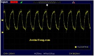
Let’s see how the signal was looking when I powered on the NE555 with the long cable on it:

Can you realize the nice noise popping around the main signal? This noise is picked up from the environment through the cable what was connected to the NE555 pin3 and of course grounded too. Here is when I used a “magic” trick without any electronic and no shielded cable.
I don’t use any electronics to filter the signal. I’m sure most of you know maybe the trick I done, but here is my “magic” :
You saw on USB, HDMI, power cables and many more sort of cables some devices like this
Maybe you asked sometime “why is this really for?” even if you know it is a sort of noise cancelling “device”. Adding a ferrite clamp to a cable at that side where the signal enters into the device is a nice trick to filter the noise what was cached through a long cable.
I done the same thing on the CNC machine and on these test on my bench too.
Check out:
As you can see, I added a couple of turn through a ferrite ring where I attached the scope and the noise was really suppressed. On the CNC machine several shielded cables was broken, the shield was no more usable. I decide to change the whole cables and put also ferrite rings just in case. They are cheap and can’t harm.
Now you can see how this little, simple trick with several turns around a ferrite ring helps as to fight the electronic dust and keep the main signal clean.
This technique with a simple scope must not have FFT function can help you not to get a headache until you try to repair a device.
I hope you enjoy this tutorial and will save lot of repair time.
This article was prepared for you by Christian Robert Adzic from Novi Knezevac-Serbia.
Please give a support by clicking on the social buttons below. Your feedback on the post is welcome. Please leave it in the comments.
P.S- If you enjoyed reading this, click here to subscribe to my blog (free subscription). That way, you’ll never miss a post. You can also forward this website link to your friends and colleagues-thanks!
Note: You can check his previous post in the below link:
https://jestineyong.com/sonic-mole-chaser-repairing/
 (96)Dislikes
 (0)
(0)
17 Comments
Leave a Reply
Cancel reply


Albert van Bemmelen
February 16, 2019 at 6:20 pm
Electromagnetic interference (EMI), also called radio-frequency interference (RFI) indeed can be hard to surpress. And in finding where it originated even harder. And using a Spectrum Analyzer is probably a very good way to find those emitting sources although you probably didn't use the FFT function on your scope to find the source. In the 50s of the previous century most mopeds interfered with the Amplitude Modulated screen of television transmissions. Causing popping up interfering spikes when they came near a TV antenna. Why they in my country then forced the owners to have installed EMI filters on their mopeds. Same thing is necessary on other induction related devices like in cars. And computers and other equipment with oscillators inside are notorious for the EMI problems they cause on other equipment like in AM radios. I do not have a Spectrum Analyzer either (they are sadly still very expensive), but I use a cheap E4000 or compatible RTL-SDR (RTL2832U) TV dongle with the free SDR# software which I am able to watch and hear all frequencies and most modulations upto about 1700 MHz (1.7GHz!). And even am able to read Pager transmissions with PDW, or receive the NOAA weather satellite photos with the same TV dongle. Of which the wave sound is converted to photos with also the free WXtoIMG program. (and the free VAC virtual Audio Cable program can be used if you do not record the wave but directly input the audio into your PDW or WXtoIMG software).
Albert van Bemmelen
February 16, 2019 at 7:48 pm
PS: I also am able to generate RF transmissions upto 4400 MHz (4.4GHz!) with this cheap Banggood module (only these black pcb boards apparently work. The other green pcb's seem to be fake!):
https://www.banggood.com/35M-4_4GHz-PLL-RF-Signal-Source-Frequency-Synthesizer-ADF4351-Development-Board-p-1129041.html?rmmds=home-mid-topicProduct3-auto&cur_warehouse=CN
And with this free application form f6kbf and a cheap Mr.Robot LCD board I am able to select and save about 20 of frequenties in memory for fast access:
http://f6kbf.free.fr/html/ADF4351%20and%20Arduino_Fr_Gb.htm
With these boards and the above mentioned free software I now was able to check at what frequency my TV Dongle stopped receiving. It was at about 1680 MHz!
Cheers!
Robert Calk Jr.
February 19, 2019 at 5:27 am
Thanks Albert! I need to get one of those.
beh
February 17, 2019 at 1:31 pm
DEAR ALBERT
Thank you so much of your very comprehensive comments about this subjects.
cheers
beh
Albert van Bemmelen
February 18, 2019 at 2:26 am
Thanks dear Beh. Glad you liked it!
Installing SDR# is a piece of cake with the instructions of this guy and the downloadlink he gives. It works great! Including installing the right TV dongle USB driver with the Zadig program:
https://www.youtube.com/watch?v=DSFIgjnkaf4
Christian Adzic
February 17, 2019 at 9:39 pm
Hi Albert!
Thank's for supporting my article.
You give a good info about the tool and the software you use for frequency
sniffing if I can call that so.
That E4000 tool looks very handy like a pocket tool in combination with a laptop.
Very interesting setup.
My best regards.
Albert van Bemmelen
February 18, 2019 at 2:40 am
It is a very helpful new tool for our electronics shack you'll love Christian! See also my answer to Beh.
I downloaded the newest version of SDR# on:
SDR# Installation : https://www.rtl-sdr.com/
But don't forget to restart your Windows if installing the dongle driver fails!
(That was what I needed to do when installing the RTL2832U-R820T driver at first failed!)
The above link to the great YouTube video to " Spectrum Analyser RTL2832U-R820T SDR# Radio Frequency Electronic Project " also shows the Mr.Robot LCD with Keypad that I also mentioned and had too build. (;)
Albert van Bemmelen
February 18, 2019 at 2:52 pm
Maybe also have a look at this Youtube video from #1nformatica that is very interesting if you also want to built a 35 MHz to 4.4 GHz ADF4351 based RF synthesizer:
https://www.youtube.com/watch?v=hYuCnsuqzjA
He probably used some bit older boards with a different pcb layout but if you buy the newer version boards the result is the same!
(my ADF4351x EVAL Board is version 2018_5_v1.3 and my Mr.Robot LCD Keypad shield is probably a version 1.0. If you have a version 1.1 Mr.Robot LCD Keypad shield you need to change the Arduino .ino file. In that case just follow the instructions in the .ino file from the download in http://f6kbf.free.fr/html/ADF4351%20and%20Arduino_Fr_Gb.htm.)
Brent Cartwright
February 16, 2019 at 11:39 pm
That it probably just high freq. noise/harmonics, saturating the waveform
Parasuraman S
February 16, 2019 at 11:51 pm
Looks like I have run out of vocabulary to describe my appreciation of your very innovative articles! What a simple, but wise solution for noise reduction! I learnt how important the ferrite core is only today! Many thanks for your wonderful article!
Lynn Blakely
February 17, 2019 at 2:37 am
To Robert: Thanks for the reminder on using the ferrite clamp to block the effects of RF, or other harmful interference. Sometime the simple solution that works, can save a lot of time. This reminds me of the definition of time. Time: "A precious commodity the price of which hasn't been established yet"
beh
February 17, 2019 at 1:28 pm
YES CHRIS you did it and congratulations.
Alvaro Rivillas.
February 18, 2019 at 12:43 pm
Good job Christian. Very interesting article.
Tejas
February 18, 2019 at 2:51 pm
Dear Chris...very important information regarding CNC. I am presently troubleshooting a Taiwan made CNC which is not able to receive programs from computer correctly. Any valuable advice shall be highly appreciated.
Robert Calk Jr.
February 19, 2019 at 5:21 am
Good job, Chris. I never throw away ferrite beads, etc.., I keep them!
Andrea Del Corso
February 25, 2019 at 11:30 pm
Good article..!!!Compliments.
Humberto
February 27, 2019 at 1:34 am
Thanks for this article, Chris.