
Part 2-FARFISA ART-482/1 door entry intercom repair. About Transformer calculations
Well, after so much of “background noise” about the transformer of the previous article of mine here https://www.jestineyong.com/farfisa-art-4821-door-entry-intercom-repair/ and in order for me to help the readers of it to obtain a better understanding of this specific task of identifying the transformers overall parameters, I considered inevitable the fact of giving some more practical information on what I did.
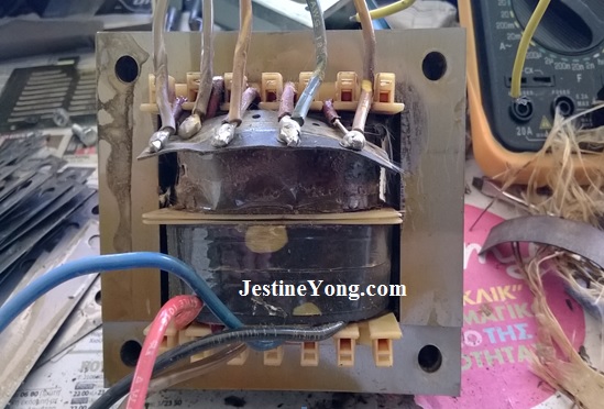
The burned transformer is shown again below:
First of all, when I opened the (EMI suppressing) side covers of the transformer’s core I noticed that it was wound in two separated parts of the bobbin. The lower one contained the two (separate) halves of the primary winding, while the upper one had all the secondaries wound there. This separation made my job of winding it off much easier than what it would be if all the windings were wound all over the core area, in layers, one after the other. The first secondary winding, that one nearest to the core, was the bi-phase winding for producing the various d.c. voltages and above it was wound the lock mechanism winding.
So, after removing the insulating papers from both windings, I immediately realized what had happened there (apart from the terrible smell of it). The external winding for the lock supply was in terrible condition with its turns stuck together. It was really very difficult to wind it off. I had to apply noticeable strength in pulling the wire. Needless to say that it was totally discolored, almost black, because it suffered an enormous overheat. Anyway I removed it and counted both, its turns and its wire diameter. It counted 50 turns and its wire diameter was 0,9mm.
At this stage I ran a “lamp test” on it. Unfortunately it was negative. The lamp was lighting in full brightness.
Then I continued with the bi-phase winding which also was a bifilar one. It counted 2×47 = 94 turns and each wire (of the two wound in parallel) had the same diameter as the previous winding (0,9mm). So this winding consisted of two strands of 0,9mm diameter enamel wire.
After the removal of the last secondary ran a second “lamp test” just to see the condition of the primary which was obviously discolored as well. Although unexpected, this time the result was positive. No light in the lamp. A sign that the primary winding had no problem.
I could stop here and simply rewind the turns of the two shorted windings without performing any calculations at all. I could buy some new enamel wire of 0,9mm diameter and that would be all, instead of dismantling completely the windings, namely the primaries that were left on the core. But this would be a mistake of mine for sure. The reason is that this overheating had already caused discoloring of the primary winding as well (and this is quite natural. To be frank, I didn’t expect to find the primary windings intact when I first saw the transformer without its insulating papers, which were really burned out, especially at their inner side, and caused such a terrible smell). So this solution would be a “short-termed” one. Then I would very soon be confronted again with the same problem.
I was convinced that this idea was correct during winding off the primary windings. They were also stuck together and many times their wire, being of thinner diameter (0,6mm), was many times cut with relatively little pulling force applied to it in order to remove it. This effect confirmed to me the correctness of the need for an overall rewinding. The two primary halves counted 412 turns each, which makes a total end-to-end primary winding of 824 turns.
Now I had all the info available and I could either rewind the same core or order an exact copy of it by giving a local constructor the parameters I found by calculations (which I will give you below).
When I contacted a famous transformer constructor here and told him what I needed, he avoided to accept the rewinding solution claiming that in my try to dismantle the core (which I failed to do because of its stuck laminations and no time to use a bath of chemicals for that purpose) I had distorted the shape of some of them and they had to be “aligned”, which would a) need time and b) be costly. When I asked him about his pricing options, he told me: “more than 30€ for “alignment” and rewinding, 45€ for a brand new unit”.
In such a case one doesn’t need to think much about making a decision. I ordered a new unit, giving him the parameters I had found. Later on I received almost a copy of the original. The core of it was of different shape only (but of same wattage) and all I had to do was to drill two new holes in the metal case which holds it.
Now about the calculations…After the second and positive lamp test, seeing that the primary was still in good operating condition, I wound 4 turns by hand in the empty space of the secondaries, using a piece of normal cable. Then I fed the transformer with line voltage, using my little variac and supplying exactly 220V a.c. Next, I measured 1,068V a.c. at the cable ends. Just for the purpose of verification and greater accuracy, I left only one turn in the core and I took a new voltage measurement. It gave me 0,267V a.c this time. So, I had already the 0,276V/turn factor in hand.
The (taken as of unknown voltage magnitude) secondary with the 50 turns in it used for the lock mechanism would now produce:
0,267V x 50 turns = 13,35Va.c. output.
The second (bi-phase winding, which mean a winding with middle point tap) would produce:
0,267V x 47 turns = 12,549Va.c. per each half, namely 25,098Va.c.
end-to end.
Next, as regards verification for the working voltage of the primary winding, this should work at a voltage level of:
0,267V x 824 turns = 220,008Va.c.
This was indeed the exact input voltage I was supplying to the primary winding through the variac.
So the overall verification as regards the working voltages of all windings was already established and the picture was now crystal clear.
One might say: “O.K, but if you couldn’t take any measurements at all, just because the primary was shorted, what would you do then”?
This is a very reasonable question which had occurred to me as well during the preliminary tests I ran for detecting shorted windings.
The answer is that I would go on with the classic method. Let me explain it below.
Having myself counted the turns of the windings, I already had their ratio. This is given by the fraction:
N1/N2 = 824 turns/50 turns = 16,48
Therefore the first secondary with its 50 turns would produce a voltage of:
220V/16,48V = 13,349Va.c. or 13,35 Va.c. as calculated above.
This holds true because the turns’ ratio and the voltages’ ratio are always equal and they form a so called “analogy”. This means in turn that:
N1/N2 = U1/U2
We simply solve this equation for U2. This will result therefore in:
U2 = U1 * N2/N1 = 220V x 50 turns / 824 turns = 11.000V * turns/824 turns = 13,349 Va.c.
Or more simply, using the turns’ ratio as a decimal number instead of a fraction and solving again for U2:
U2 = U1/ 16,48 = 220/16,48 = 13,349Va.c. again, as above.
What is missing now is a correction that should be done, due to the fact that I was testing with a voltage of 220V exactly, while the primary winding was designed for a maximum input of 254 Volt.
Solving the same equation formula as above, we have:
U2 = U1 * N2/N1 = 254V x 50 turns / 824 turns = 12.700V * turns / 824 turns = 15,41Va.c. for the winding feeding the lock mechanism.
And also:
U2 = U1 * N2/N1 = 254V * 47 turns / 824 turns = 11.938V * turns / 824 turns = 14,48Va.c. for each half of the second secondary winding, or 28,96Va.c. end-to-end voltage.
When I ordered the transformer, the nominal voltages I gave (for 254Va.c. input) were 15,5Va.c. for the first and 14,5V+14,5Va.c. for the second winding.
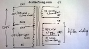
I also gave the man a drawing of its internal circuit (drawn by hand) as shown below.

Now, as regards the currents of the windings:
Both the secondaries had the same wire diameter of 0,9mm, with the bi-phase one being also bifilar.
At this point it would be helpful I think to inform you about the industry standards related to the wire diameter in relation to the working mode of the transformer in its real life.
A transformer designed to work round the clock, as it is expected, has different design than another one of exactly the same type which is intended to work only for a few hours per day.
The provision usually applied on the purpose to increase the longevity of a hard working transformer is to give it a plus percentage in its turns’ number as compared to their exact calculated number. Both the primary and the secondary windings should be given this equal percentage.
Along with this and similarly doing, a plus percentage is given to the wires’ diameter as well. The total result will always be a much more comfortable round the clock operation of the transformer, in terms of the magnitude of the temperature it will develop under nominal loading. I think that the reasoning is easy. Increasing the wire thickness, its resistance decreases. This in turn decreases further the copper losses of the winding as the voltage drop in the Ohmic component of the winding is also reduced accordingly.
All of these above mean that in the second case, the current density standard we take for assessing the cross sectional area of the wire (and therefore its diameter) is 2,55A/mm2.
In the first case, where the transformer has to work round the clock, we take lesser current density, say 2A/mm2 or even lesser, depending on the case. About that you can find relevant data in various tables included in books or in the web.
Next, what we need first is to calculate the cross sectional area of the 0,9mm diameter wire used in this case, in order to assess afterwards the maximum permissible current flow through it.
So if we take the usual 2,55A/mm2 standard of current density factor in account, the cross sectional area of this wire is given by the formula:
S= π * R2 = 3,14 * (0,9mm/2) 2 = 0,636mm2.
And the permissible current flow through the wire is given by the formula: S= Io/δ, whereas δ = 2,55A/mm2 = current density factor.
Thus: S= Io/δ and then solving for Io:
Io = S * δ = 0,636mm2 * 2,55A/mm2 = 1,62A
This is the maximum permissible current of the door lock winding. Do you remember that the fuse rating of this winding was exactly 1,6A?
For the bi-phase and also bifilar winding, since two strands of the same wire diameter were used, we will have as maximum permissible current flow through them the double value found previously, namely 3,24A.
Now it is time to calculate the total secondary power:
1st winding: 15,5V * 1,62A = 25,11V*A
2nd winding: 29V * 3,24A = 93,96V*A
And the total Psec is: Psec = 25,11 V*A + 93,96 V*A = 119,07V*A
Assuming now an efficiency of 85%: 119,07V*A/ 0,85 = 140 V*A (worst case)
Note that the cross sectional area of the transformer core as I measured it was:
3,7cm * 3,9cm = 14,43 mm2.
The assessed power above calls for the use of a transformer having a cross sectional area of:
S = 1,2 * √Ptot, whereas Ptot = 140V*A
Thus substituting Ptot and solving for S:
S = 1,2 * √140V*A = 14,2 mm2
That is the cross sectional area needed for the transformer to be used.
Since the resultant value is smaller than the one established by the physical dimensions of the cross sectional area of the used transformer, this means in turn that its core could handle this power absolutely safely.
Now as regards the current flow through the primary winding, this will be of the order of: 140V*A/ 230V = 0.609A, or 609mA.
The wire diameter chosen by the factory was 0,6mm. Is this diameter suitable to handle the primary current shown above? Verification:
This diameter gives a cross sectional area of: S= π * R2 = 3,14 * (0,6mm/2) 2 = 0,283mm2.
Thus: S= Io/δ and then solving again for Io: Io = S * δ = 0,283mm2 * 2,55A/mm2 = 0,722A, or 722mA, which means that the wire size chosen for the primary is adequate in order to handle the reflected secondary load on it plus the total losses. In fact it will work with the 84,46% of its maximum permissible value.
Hopefully this analysis will answer all the possible questions you might have after reading my previous relevant article.

This article was prepared for you by Paris Azis from Athens-Greece. He is 59 years old and has more than 30 years’ experience in electronics repairs, both in consumer and industrial electronics. He started as a hobbyist at the age of 12 years and ended his professional carrier as a senior electronics technician. He has been a specialist in the entire range of consumer electronics repairs (: valve radio and BW TV receivers, transistorized color CRT TV, audio amps, reel and cassette tape recorders, telephone answering and telefax devices, electric irons, MW cooking devices e.t.c) working in his early stages at the official service departments of National-Panasonic first and JVC afterwards, at their premises in Athens.
Then he joined the telecoms industry, working for 20 years as field supporting technician in the sector of DMRs (: Digital Microwave Radio transmission stations), ending his carrier with this subject. Now he is a hobbyist again!
Please give a support by clicking on the social buttons below. Your feedback on the post is welcome. Please leave it in the comments.
P.S- If you enjoyed reading this, click here to subscribe to my blog (free subscription). That way, you’ll never miss a post. You can also forward this website link to your friends and colleagues-thanks!
Note: You can check out his previous repair article below:
https://www.jestineyong.com/konig-pa-10000-amplifier-repair/
 (83)Dislikes
 (0)
(0)
27 Comments
Leave a Reply
Cancel reply


Robert Calk
October 23, 2015 at 10:57 am
Nice work, Paris.
Also for anyone that may be interested, I found this handy little L/C/F Calculator that is a good tool for winding inductors and single layer coils.
http://www.arrl.org/shop/L-C-F-and-Single-Layer-Coil-Winding-Calculator
Gerald
October 23, 2015 at 4:54 pm
Hi Robert,
There is a great apps called ElectroDroid for smartphones. It has all those calculators such as inductor design tools and filter calculations etc...
Cheers,
GM
Albert van Bemmelen
October 23, 2015 at 7:46 pm
Thanks Gerald, that app amongst several others including finding SMD codes, I sometimes also use. Good to know those apps are comparable in functionality.
Robert Calk
October 23, 2015 at 10:37 pm
I don't have anything very personal on my "smart phone"(NSA spy tool). I don't even have my main email on it. And to be honest, I liked my "dumb phone" much better.
Albert van Bemmelen
October 23, 2015 at 4:59 pm
Thanks Robert, I copied your link. Is very interesting but because I can't see what the program looks like I'll wait before buying it.
Robert Calk
October 23, 2015 at 10:34 pm
It's not a program - it's a card type that you slide the center card back and forth to line up to find what you are looking for.
Albert van Bemmelen
October 24, 2015 at 3:00 pm
Okay thanks Robert. So it isn't a program but a 'paper calculator' from the guys from ARRL. Clever because that one works without pc or batteries.
Paris Azis
October 24, 2015 at 1:06 am
Thank you Robert.
Best Regards
Yogesh Panchal
October 23, 2015 at 1:57 pm
Good explanation! thanks for sharing informative notes.
Paris Azis
October 24, 2015 at 1:12 am
Thank you too Yogesh.
I hope that this article will help all of those readers interested in this subject and need either to rewind a burned transformer by themselves or modify an used one so that it will produce different output voltage(s) or current(s) within its power rating.
Best Regards
Albert van Bemmelen
October 23, 2015 at 4:47 pm
Fantastic and unique explanation Paris! Thank you very very much!! This is something we very rarely read about.
The theoretical part is very clear to me now. (I noticed that you kept the European way of writing down numbers using a comma instead of the American decimal point notation.)
It is really remarkable what you are able to accomplish by dismantling an almost 25 year old cooked Transformer. In the Reverse Engineering way you had done this.
And the fact that the famous transformer constructor wasn't keen on rewinding an old smellie transformer was probably a good reason he supposedly told you that you had distorted the shape of the laminated core. Which you probably didn't? But it nevertheless still would have been 15 Euros cheaper to have him re-aligned and rewound the old core.
It is not very clever of the Manufacturer not to mention the secundary transformer core voltages with a information sticker of some sort, and it therefore is remarkable that you did menage to find the maximum primary winding voltage.
Also this "transformer designed to work round the clock part thing" is very interesting since the price of the necessary extra wire length for the extra turns would be close to nothing!
But because you also explained the second possibility to use thicker wiring, than it will be more costly of course.
Until that part I understood every word, and the formula's you used I probably had seen before very long ago. But everything you wrote after this is completely new to me and I will keep your article as concise information about transformers!
I only ask myself what your famous local Transformer constructor is using for chemical bath when he starts dismantling any old core. And how far he takes this alignment of the laminations thing. And what paper and glue he will be using to finalize the windings on the transformer core.
And I know that in Amplifiers they also often use a special metal mantle (Copper or Mu metal?) to cover the complete outside core of the transformer in order to eliminate the 50/60Hz AC frequency coming into the amplified audio channels.
Paris, thank you again very much for taking the time in explaining this difficult task of analyzing a Transformer.
I only can conclude in saying that you are a remarkable Great Transformer EXPERT !!
Albert van Bemmelen
October 24, 2015 at 3:45 pm
Hi Paris, I've still got a material question left. Something that I wondered about all along, but that still wasn't physically mentioned. If the famous local transformer is able to re-align the transformer core, after this special chemical bath, is he then also able to open up the core? I mean: Can he then also remove the primary and secundary coils from the core, Without unwinding them first? Seeing your photo of the transformer it looks like he can. And both the primary and secundairy windings are wound on a separate plastic bobbin. That looks detachable. Since the core looks like a M that is closed at the bottom by a single underline.
And if you've ever done this task succesfully at home by heating the core to a temperature were the Glue gets kind of liquid? Sorry I ask, but I've also never build one before. And this 'Core' part somehow wasn't mentioned.
Paris Azis
October 24, 2015 at 4:49 pm
Hello Albert
Yes, after the chemical dissolving bath it’s much easier (and of course easily feasible) to dismantle the core by removing its laminated elements.
After that the removal of the coils is also much easier, but the winding off process is unfortunately unavoidable. This is due to the fact that the bobbin has always stopping ends and therefore the coil cannot be removed altogether. It must be wind off turn by turn. For an organized laboratory that performs such tasks this job is easy. They put the bobbin in an axle passing through its core space a piece of wood having the same dimensions of the transformer coil (all cores are standardized and therefore these labs usually have an entire set of wooden artificial cores for this job). Then, this axle passes through the artificial core (across it) an it is then attached to the winding machine, only this time the electric motor is disabled and the technician winds the coil off by simply pulling the wire as the axle spins now freely. That’s all. In cases of very small transformers which have very-very thin wire in the primary winding, the alternative is to remove it by cutting it across the direction of the axle and remove it in layers. This is the easiest way. Nevertheless, as I have seen this process many times in the past, these technicians just because hate working with calculators and mathematics they always prefer to remove the coils by winding them of turn by turn and see their count on the mechanical or digital counter embodied to their winding machine.
I have many times opened even impregnated cores but I have never heated their cores. I did this only when dismantling ferrite cored transformers. You cannot open them without heating them.
Finally, instead of feeling yourself sorry, feel free to ask me what you want. This is no problem to me (if I know the answer)!
Best Regards
Gerald
October 23, 2015 at 4:51 pm
Good stuff Paris. It reminds me the time I was rewinding old radio transformers, removing the 250V secondary (used for vacuum tubes plate voltage)and rewinding for 12V or 24V... for my experiments.
Thanks for sharing.
Cheers,
GM
Paris Azis
October 24, 2015 at 1:17 am
Hello Gerald
Exactly for this purpose I have written this article. (Take a look please in my answer to Yogesh above).
Thank you for your support.
Best regards
randy
October 23, 2015 at 11:41 pm
Excellent and very informative, electronics theory and application at its best!
Paris Azis
October 24, 2015 at 4:50 pm
Hello Randy
Thank you for your positive comment.
Mahmoud
October 24, 2015 at 1:29 am
Hi my dear friend Paris i thanks a lot for a long time you did and explain how to repair transformer.now my question to you is it was not better you buy a new trans..and you have not spent so much time?
hope you are well
Paris Azis
October 24, 2015 at 5:00 pm
Hello Mahmoud
Thank you for your supporting comment. As regards your question, keep in mind that I could not order a new transformer without having myself any idea about the output voltage and current of its second secondary winding. Therefore this work was mainly a matter of obtaining the vital overall information in order for me either to proceed in a repair or to order a brand new unit afterwards.
Regards
Henrique Jorge Guimarães Ulbrich - Brazil
October 24, 2015 at 2:14 am
Very good, Azis. Congratulations on the noticeable clear and concise way used for the explanation and also on the effort to save one more equipment from junk. Indeed, it can be noticed that your maintenance works are generally really epic.
Paris Azis
October 24, 2015 at 5:01 pm
Hello Henrique
Thank you for your warm and supporting comment.
Best Regards
Paris Azis
October 24, 2015 at 2:45 am
Hello Albert
Thank you too for your warm and supporting comment.
Yes, I use comma in mathematics because this is what I have learned at school already from my childhood. I cannot change it now!
Well, as I already told you, I did this rewinding job so many times in the past that I am used to it and therefore I am very familiar with it. Of course the classic transformer tends to disappear from the modern power supplies. Along with it the old linear PSUs follow the same way giving their place to SMPSes.
Times change and electronics change as well…”Once upon a time” I was an expert in vacuum tube technology…Fortunately the C.R.T era in TVs lasted too long compared to their rest vacuum tube circuitry which started relative very soon to become first transistorized and then consisting of ICs, and I had the chance to enjoy this very simple and easy technology. On the other hand, this period was the most profitable for the professionals as the troubleshooting itself was much-much easier. I still remember (and I will never forget) many characteristic failure cases in B/W vacuum tube circuitry…Sound problem? PCL 86. Vertical problem? PCL85. H.V problem? PL504, PY88, TV 18 (H.V rectifier diode)…
As regards this transformer, yes some (I) laminations were simply bent. (E) was only one as I remember but one way or another I had removed very few from the core because they were stuck.
I know that it would be cheaper to let it for repair but the pressure I had for fixing the system didn’t allow for any delays. I could have the new built unit much sooner and I chose this solution.
I agree with you about the info on the manufacturers’ part, but this, especially nowadays, is a dream! Soon you will see details about that LG TV I repaired “in blind” again, doing something similar to this transformer…
As regards the bath that dissolves the impregnating substance, I also don’t know what chemical it contains, but I think that it is easy to find this out. I will try to ask a friend of mine who is specialist in electric motors’ rewinding. Maybe he has an answer. Enamel for transformers I know that we can find in spray form, as the rest ones we use in electronics. The paper they use is also very common. I thing that they call it here in my country “prespan”. I guess its name has French origin.
Yes, for transformers designed to work round the clock it was a common trick the manufacturers always applied to increase the wings’ turns by a percentage of 20%. This helps the transformer to work better in terms of temperature development within it.
Finally yes, in audio circuits it was a common practice to use a copper film equal to the internal dimension of the height of transformer’s core and having it wrapped and shorted as a single external turn around the core. This is an effective noise suppression method. Anyone can always add this as an improvement in case it is missing from a transformer, or if the transformer is open without covers. Anyway great care must be taken in the detail that this copper film must be put externally and not internally (namely directly wrapped on the core).
Before closing, I owe you (and our readers as well) an apology in that I kept wrong info in my memory when writing the previous articles, regarding the energy reserve of the 12V winding for the lock. This was wrong. There is no energy reserve. The winding was calculated from the manufacturer to give maximum (fused) current of 1,6A, but no more. This winding was not bifilar as the other one, but I missed this. That’s why I mentioned about that (non existing) energy reserve for this winding. And on the other hand this is the reason that it melted so badly after the bridging of its fuse…
Thank you again for your support.
Best Regards
Albert van Bemmelen
October 24, 2015 at 4:24 pm
Thanks again Paris for all the time you took to make a very interesting article about those so frequently everyday used transformers!
I didn't see your answer until now. Sorry for that,
but that's why I asked another question under my previous Post instead under your recent answer above. I could also ask you another question about how to understand the extra energy in a coil thing.
But I guess that the bifilar winding just means that you get the same coil twice and so at twice the Amperage. (3,2A instead of 1,6A)
If you ever do find out the chemical substance which is used to dismantle a transformer constructor you probably also can help Mark (from Australia) who asked me previously in a Post how to best remove old layers of varnish paint.
And thanks for the great article!
Paris Azis
October 24, 2015 at 10:04 pm
Hi Albert
As I told you, feel free to ask me questions. If I know the answer I will answer it. And yes, this is what I meant by saying about energy reserve of the coil. As for the chemical, I will ask for help from experts on the topic. Anyway burning is the usual method as regards the electrical motors (as I have seen), although this is against the internationally used common practice which always makes use of dissolving baths.
Best Regards
Anthony
October 24, 2015 at 8:18 am
Hi Paris,
Fantastic detail and a thorough explanation of your analysis techniques. It's a great pleasure to read your articles !
Thank you for taking the time to share these with us.
Best regards to you Sir.
Paris Azis
October 24, 2015 at 5:09 pm
Hello Anthony
Your warm and supporting comment is also a pleasure for me, encouraging me to continue sharing my experience with you (along with all the other readers).
Best Regards
Anand Palkar
October 25, 2015 at 11:58 am
Hello Albert,
Nice article, I appreciate your good work in putting down all the resources and finding during the process . Removing the EI CRGO lamination is not so difficult as you said , You can soak or apply kerosene or turpentine or any paint thinner by brush to the staked lamination for some time and apply some more till it completely soaks in.Press the staked lamination bunch by hand and if you see bubbles coming out when pressed it time to remove the lamination. If you dont see any bubbles soak for some more time.
To remove the lamination use a knife or a steel sheet of same thickness or less thickness when compared to the lamination thickness. The entire process takes 3 to 4 hrs but rewinding is a good option because you save a lot of money in our part of the world 40 Euros is very expensive.
Thanks for taking the time for sharing
Best Regards
Anand Palkar