
Servicing and Modifying JVC-RC-EX40V Three-in-one

This set was brought to me with the complaint that there were crackling noises and the set worked only after hitting it a few times (very unhealthy practice, of-course!). The customer also wanted to have USB player added to this.
This set has Radio (FM/AM/SW), CD player and Cassette player all three in one. I opened the set, dismantled it and cleaned the inside thoroughly using blower and various suitable brushes, as the inside was full of dust! Brought it to my service table. Have a look at the inside:
Noticed that the reason for loose contact was dry solder under the Power Supply connector. This set has the Transformer, power supply components like Diodes, Capacitors and other filters fit on the rear cover with the +/- connector. Similarly the front portion houses the Cassette Deck, Control board for CD and volume control and also the two speakers. The Tuner is a separate Board. So is the control board. Volume control is on another board. The Cassette Deck has one board fit on its rear, housing the preamp and recording circuit. From all these boards there are inter connectors. The strip wire that comes from the CD eye unit is so short that we cannot remove it or replace it using hand. We need an extended thin nose player to do this, and we have to be very careful and gentle. Since the strip wire was in a bad condition, I replaced it with a longer one for easy reassembly.
There were no ESR problems of Capacitors on power supply section or on the main board. So, I did a dry solder patch up on all boards. Assembled the set back except the rear portion. The customer wanted to have a separate unit for USB that can be connected to this set, as he preferred not to spoil the look of the set by fitting the USB Player unit on it. Since this set does not have an audio in socket, with the consent of the customer, I decided to use the Audio out sockets from the CD, provided at the rear of the board to convert it as audio in. The customer did not want to use the Tape Deck and therefore, I decided to use the Tape Function for USB.
So, I removed the audio signal connector that goes to the deck, for taking out its left and right channel in. I removed the + red wire of motor from the four pin connector, tied it on the connector wire and taped it. Left the leaf switch (which controls the power supply to the tape deck) sockets in it along with the – black wire (I did not remove the black wire as it is the ground and mechanism and other metal parts would have got grounded through this to avoid noise pickup). Disconnected one end of the two resistors that go to Left and Right Channel Audio out sockets and bent it up safely. Whenever I do any modification to meet customer’s need, I never remove any components or other parts from the set. What I do normally is to disconnect that potion and leave all these in the set for any possible reversal in future.
Connected a two way shielded wire on it choosing red for the right channel and black for the left channel. Routed it through an unused hole near to the Audio Out Sockets and brought it through another unused hole on the PCB near to the signal connector of Tape Deck. Soldered the hot ends to the removed leads observing the left and right channels and grounded the shield to its black wire. You can see the work done in the following pictures:
The marking of left and right channel on the connector was done after locating the input points by switching on the set, selecting function switch to tape, and touching each point in connector with a needle. After doing this internal wiring, connected audio in from a USB player that I normally use for testing purposes. It worked very well.
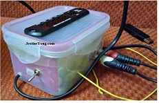
The next work was to assemble a USB player using the readily available Chinese Panel Board, which has FM Radio, Aux in and USB in and comes with a full function remote, as there are no keys on the panel. I bought one good and sturdy box from a super market nearby. Since the customer said that his wife used the set in kitchen, I selected a box that will go well with the cutlery and vessels normally available there! Cut hole on its lid, for inserting the panel from the front and screwed it in place. Then fixed a 230V to 7.5-0-7.5 V AC (500mA) transformer on its side, leaving room for the component side PCB of the panel. Drilled holes for two RC sockets and fixed it and soldered its ground together. Drilled hole for the mains cord and inserted it and tied a knot inside so as to prevent accidental pulling out. Drilled a suitable hole and fixed the AC in on/off switch (Single pole two way). Connected the Line wire (Red) to it through a 1A Fuse. Connected one end of the primary of Transformer to the other way of the switch. From the secondary, soldered the centre tapping on the Transformer metal shield.
This will not only work as a DC Power supply holder, but also enable filtering noise and hum. From that point, soldered a fairly thick cut lead and on that I fixed the negative lead of a 2200uF/25V Capacitor. On its positive lead, connected anodes of two IN4007 diodes, and connected the cathodes to each of the 7.5 V AC leads (secondary) of transformer. Connected the input lead of IC 7805 (which had a heat zinc fixed on it) to the junction where the anodes and capacitor positive are joined. Fixed its centre pin to the ground and connected a 220uF/25V to its output. Thus the basic requirement of 5V DC for the USB Panel Board was made ready. Then, connected the two wires coming from the Power Supply in of the panel to the 5V DC output.
Connected the ground, left and right channel wires to the RC Sockets. (Red for right channel and White for left channel). Left a note near the TX warning about presence of 230V AC, though I had covered all the exposed parts with insulation tapes. (I normally warn the buyer always about children fiddling around with such assembled devices). Now you can see all these in the following pictures:
Fixed the back cover of the set and put back all the screws firmly, and covered screw holes with tape to avoid wasps building ‘homes’ for its larvae!
Here is the set after finishing all work and in-house rigorous testing of all functions. You can see two pictures, in one, the CD working and in another working on external USB.
Thus a very nice service work mixed with assembly was completed to my utmost satisfaction!
This article was prepared for you by Parasuraman Subramanian from India. He is 68 years old and has more than 30 years’ experience in handling antique equipment like Valve Radio, Amps, Reel Tape Recorders and currently studying latest tech-classes conducted by Kerala State Electronics Technicians’ Association. He has done graduation in BBA degree, private diploma in Radio Engineering and retired as MD of a USA company. Presently working as Consultant to Hospital and other institutions.
Please give a support by clicking on the social buttons below. Your feedback on the post is welcome. Please leave it in the comments.
P.S-If you enjoyed reading this, click here to subscribe to my blog (free subscription). That way, you’ll never miss a post. You can also forward this website link to your friends and colleagues-thanks!
You may check on his previous repair article below:
https://jestineyong.com/servicing-sunma-yx-3600treb-analogue-multimeter/
 (57)Dislikes
 (3)
(3)
14 Comments
Leave a Reply
Cancel reply


Mark
October 3, 2017 at 9:40 am
Well done Parasuraman!
You had the opportunity to think outside the box - or was it inside a box?
Parasuraman S
October 3, 2017 at 1:42 pm
HA! HA!
Justice
October 3, 2017 at 1:05 pm
Mmmm Parasuraman that is an excellent information to read over and over again, tnx.
Yogesh Panchal
October 3, 2017 at 2:27 pm
Good Job! Sir
James
October 3, 2017 at 4:17 pm
gOOD sTUFF 🙂
Suranga Electronics
October 3, 2017 at 10:41 pm
Ha..Mr,parasuraman ,
Good Solution for the CD Rc portable. Nice repair.
Robert Calk
October 4, 2017 at 2:30 am
Good job, Parasuraman.
Albert
October 5, 2017 at 5:06 pm
It is a kind of bypass surgery you've managed to pull of here Parasuraman! (speaking in hospital terms as to you working as a consultant or repair-engineer at Hospital and other institutions).
I would not wonder if any customer is so happy with such a new USB mp3 player (with radio receiver) you've made that they would like you to make another one of these working stand-alone added to a small PC stereo audio amplifier.
Parasuraman
October 6, 2017 at 12:19 am
Ha! Ha!
Parasuraman
October 6, 2017 at 12:23 am
I have been making this USB/FM player for quite some time now. I would have made around a dozen of them for my customers!
Albert van Bemmelen
October 6, 2017 at 12:48 pm
I had no idea these USB/FM mp3 player carkits were so affordable Parasuraman. So yesterday after reading your article I also bought two of those kits on Aliexpress. Thanks!
shiva
October 6, 2017 at 1:09 pm
Dear Sir,
Great Job.
kindly inform me about How add the USB in old CD Player step by step.
thanks & regards
shiva
Bangalore.
Parasuraman S
October 16, 2017 at 7:04 am
Shall revert.
Steve
October 23, 2017 at 5:52 pm
Excellent work sir.