
Tektronix 2440 Oscilloscope Repaired
My good friend and old colleague Frans brought in today a Dual Channel Tektronix 2440 Oscilloscope that short circuited on the Wall Outlet by also destroying the internal 4A 230V Fuse when the Power Button on the Scope front was pressed.
So he asked me to have a look if it was fixable. I myself own a 4 channel 350MHz Tektronix 2465a Scope that did cost me a lot of money to get it. And since my friend got his Scope from a good friend of his for free, I think he is very lucky to own one too!
I therefore instantly checked powering on his Scope by using the well known Bulb trick (a 75Watt Bulb inbetween one of both 230Volt AC power cable wires) to safe the Scope from further blowing up parts when it indeed short circuited again. And the burning Bulb proved that there still was something short circuiting probably inside the Power Board.
So next photos show how I opened the Tektronix 2440 Scope to inspect the cause of the Power problem. And why the Scope didn’t turn on except for only some blinking of the 3 yellow GPIB leds on top of the scope CRT tube and also visible on the front of the Scope. And my friend told me that the Scope supposed to have some Network cable problems also, why the previous owner probably disconnected the internal power plug (normally connected on the Power Board to J166) to Flatcable connector J150 going to one of the side boards.
Above photo shows the top Board of the Tektronix 2440 Scope that has to be opened to be able to inspect the Power Board underneath.
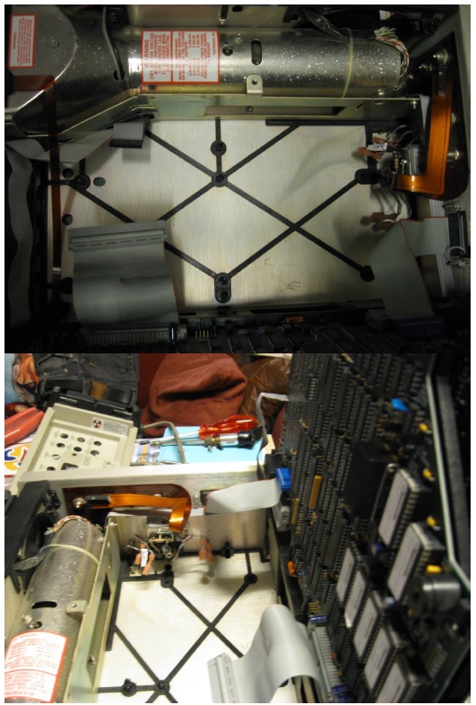
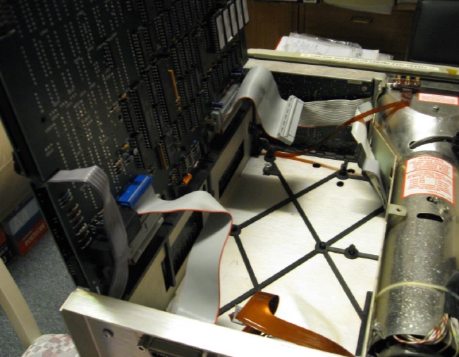
Above Photos show the black plastic holders on which the Power Board was attached. Only one metal Torx screw on the left of the board had to be removed to be able to extract this Board for inspection. Plus one long screw that was attached to the Power Board Metal in the middle from a hole in a board on the side. And on the right of the Power Board the 2 x 2 input wires for the 230V and 115V AC input selector had also to be removed. (Plus a few other flat cables were carefully loosened making it easier to open the Top Board).
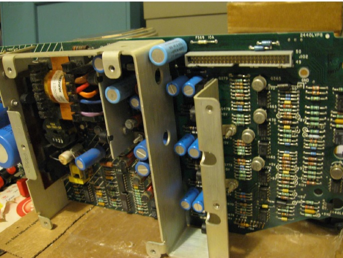
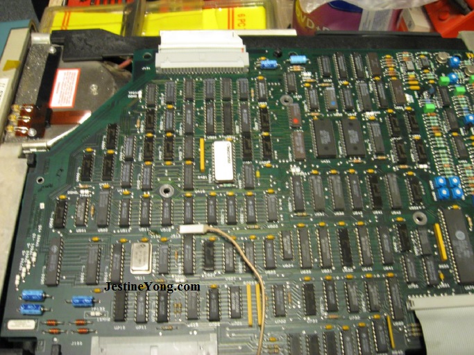
On above Photo the for inspection removed Power Board is shown. I thought to find some short circuiting or exploded Capacitors but there were none! After some further inspection I noticed that the Rectifier Diode Bridge was shorted between pins ~ and – . So I removed the Bridge. On the right side of this Power Supply Board (or the Low Voltage Supply Board as Tektronix calls it) is the Voltage Output side were + and – 8V,15V and 5V can be measured. On this side there also is a 10 Volt Reference Voltage. And a unregulated 5V Voltage (5Vd) that is secured by a 10A Fuse (F296). All Power Board Fuses were still intact. So only the Scope Main Voltage Fuse (4A Fast 230V AC) and the Greatz Fast Recovery Diode Bridge were Blown. Also on this board Right under there is a 4 + 5 Pins connector holder for the High Voltage CRT Board. But only the J102 Flatcable connector on the right top side caused problems when connected to all other boards. The AC input selector of the Scope was very simpel and worked like this: The 230V – 115V AC selector only connected two wires P70 and P80 on the board when in 115V mode. In 230V AC mode (and in 115V AC mode) two other wires P30 and P60 connected the 230V AC voltage input wires directly to the Board after the attached input Fuse and the On/off switch were activated. So only in 115V selector mode P70 and P80 were bridged on the Supply Board together also.
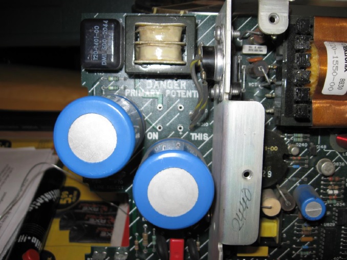
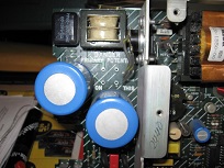
On above photo you see the place were the Fast Recovery Bridge Rectifier was connected (CR510 in the Service Manual 3A 600V, page 476 in schematic and page 395 on the component list). Above the second Big Electrolyte Capacitor on the right. Many Service Manuals including for the Tektronix can be found on http://www.textfiles.com/bitsavers/pdf/
The Fast Recovery Diode Bridge for Tektronix Model 2440M only, is a type RKBPC606 600V 3A (6A according to Manufacturer!)
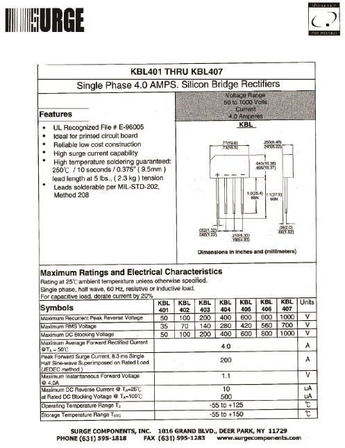
Since I had no Fast Recovery Rectifier Diode Bridge I replaced the RKBPC606 by a KBL405 that easily can handle 4A at 600V (and about 200 Amps in short bursts!). Also to be able to quickly find out if it was wise to continue my repair.
On next photo the Bad original Fast Recovery Diode Bridge is shown, after removing it from the Power Supply Board.
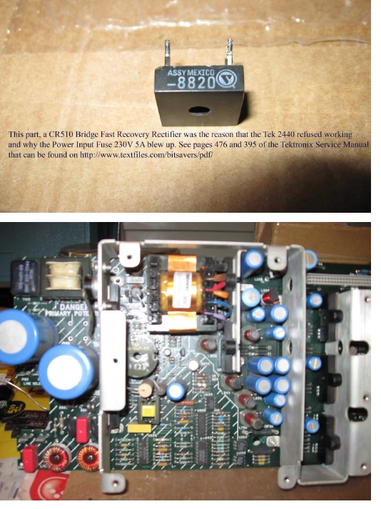
On previous photo another view on the for inspection from the Tektronix 2440 extracted Power Board.
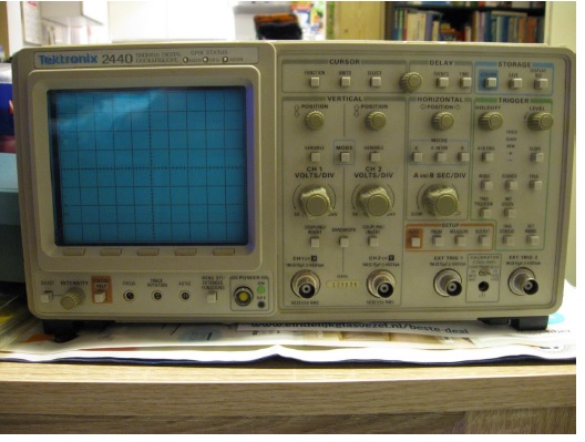
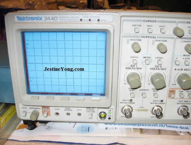
And above photo shows the 2440 Scope front with the 3 mentioned GPIB Leds and the Power PushButton just left from the first BNC Channel input connector.
Because I couldn’t exactly pinpoint were to find the problem why the Power Supply kept working in Bursts, I had removed all boards that were connected to Power Supply Connector J102. And after that the Power Supply worked uninterrupted as also the big loud 12V Fan did.
So it seemed that the Power Supply Board was okay now after replacing the Bad Diode Bridge. But to be sure I checked all regulated and/or unregulated Output Voltages while adjusting the input AC voltage with my Variac from 0 to 240 VAC. (This time without any 75Watt Bulb inbetween). And all checked out to be Fine! So the Power Board had previously short circuited but now wasn’t the problem anymore.
I also had checked the High Voltage PCB for the CRT tube and couldn’t find any shorted components or problem. And I already noticed that when it was connected to the earlier mentioned Powerboard 4 + 5 Pins, it did not cause any problem.
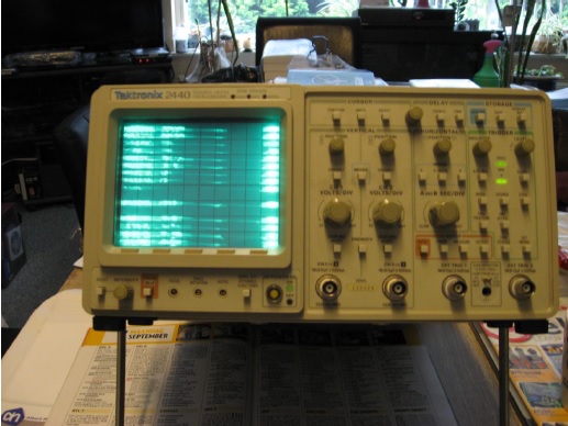
So when I finally a day later brought the Tektronix 2440 Scope back to Life, I first only left the smallest Flatcable connector of the Biggest Board with all Hybride Chips unconnected from the Power Supply. And noticed that some of the Leds on the Front started working. (triggering mode Leds). First with my Variac to a maximum Voltage of only about 140 VAC. And later on also on the
230 VAC Mains. And only when I finally got all Connectors Powered by the J102 connectorplug on the Power Supply Board (or the Low Voltage Supply Board) also the CRT Tube became visible. (Which made me very happy!)
Next the Datasheet of the 600V 4A Diode Rectifier Bridge I used to repair the Tektronix 2440 Scope.
(I had to bend the Leads a bit to Fit in the Power Board. But it was quite easy).
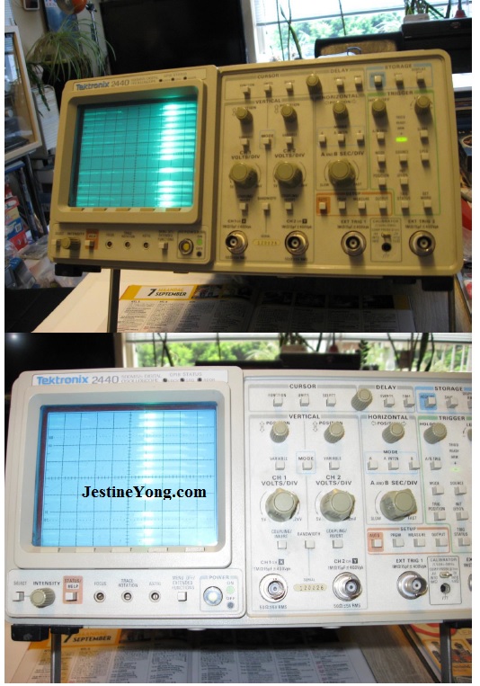
I guess it now only is re-calibrating time to get the scope in usable condition again. Because the internal Memory Chips on the Board with the 3.5 Volt Lithium (Black Keeper Battery) are constantly powered at 3.5 Volt but maybe do not hold the right data anymore?
And I read on YouTube that some people had to reset or re calibrate their Scope entirely to get rid of the jumping Characters and wrong Settings on the CRT Scope Tube.
And I hope for my friend that it is not the very expensive Hybride Board in the Tektronics 2440 500MS/s Scope that is the cause of this. For now my job is done. Another valued and expensive device repaired! Hope my friend is happy and that he, or one of his Radio Amateur Hobbyist, will be able to Calibrate or Re-Configurate the Scope to almost new again.
So much for now. Hope to write some more next time !

Albert van Bemmelen, Weert, The Netherlands.
Please give a support by clicking on the social buttons below. Your feedback on the post is welcome. Please leave it in the comments.
P.S- If you enjoyed reading this, click here to subscribe to my blog (free subscription). That way, you’ll never miss a post. You can also forward this website link to your friends and colleagues-thanks!
Note: You can read his previous repair article below:
https://www.jestineyong.com/kodak-photoprinter-repair/
 (123)Dislikes
 (2)
(2)
25 Comments
Leave a Reply
Cancel reply


Chris
September 12, 2015 at 1:26 pm
Congratulation Albert, nice job done and a good scope was saved.
I hope your friend was happy too.
Well done.
Thanks for sharing.
Albert van Bemmelen
September 12, 2015 at 3:31 pm
Thanks Chris. Although I brought the 2440 Scope Back to Life after fixing the dead Power Supply it probably still needs new Hybride parts. Or maybe a new Hybride Board. As I predicted worsed case scenario in the article. Because only the Intensity CRT tube potentiometer and the Scope Buttons do work. And it all has to do with some problem on the 5Vd line from the Power Supply Board to the Hybride Board. Although the original F269 5Vd fuse (10A) is okay it seems the be short circuiting. I probably need a new Hybride Board to correct it. And is maybe also the cause why the Diode Bridge got defect. The short is not on the Power Board itself! I checked this by connecting an external 5V Power Supply to 5Vd on the Power Board. And only when connector J102 to the other Boards was attached on the Power Board there was a very low Voltage of about 2.25 Volt. Without J102 connected there was a stable 5.20 Volt on the Power Supply! The transformer coil AC voltage for the 5Vd line was with 9 V probably too high now. The dual rectifier diode for the 5Vd line to the F269 (10A) Fuse was stil fine however! So I did Fix the dead Power Supply but probably need replacement Boards or new Parts to Fix the Tektronix 2440 Scope. And that all depends on the Price Tag. By-the-way : The 5V line voltage on the A12 Processor Board, measured over the TTL components, was Fine! So I am almost certain it can't be this Board that's causing problems. Knowing the fact that these old but reliable Scopes are becoming very affordable by the day it is only a question of waiting for the right moment to buy spare parts.
Albert van Bemmelen
September 12, 2015 at 7:34 pm
PS: The Sytem I/O Board seems to operate fine too! Because the Loudspeaker on it (that also is Powered from the +5Vd Power line) just like the 555 chip U274 that generates the sound, and U754 a 74LS273 that activates the three GPIB Leds mentioned in the article, all work splendid.
Yogesh Panchal
September 12, 2015 at 2:44 pm
well done sir and thanks for sharing.
Albert van Bemmelen
September 12, 2015 at 11:43 pm
Thanks Yogesh. My friends keep me busy with bringing me interesting new devices to fix. Like this nice piece of Tektronix 500MS/s Oscilloscope. So there is never a dull moment wasted!
Anthony
September 12, 2015 at 6:12 pm
Very good job Albert and please let us know the progress of the scope's resurrection.
Paris Azis
September 12, 2015 at 11:11 pm
Hello Albert
Good job! Thanks for sharing this experience.
Best Regards
randy
September 12, 2015 at 11:05 pm
nice work, real electronics repair! I have a Tek 540C that I need to get working if possible, has the dreaded bad SMD caps problem and will require all SMD caps removed, not fun!
Albert van Bemmelen
September 13, 2015 at 9:00 pm
Hi Randy. Maybe this Link does help? http://www.eevblog.com/forum/testgear/tektronix-2465b-oscilloscope-teardown/
It is maybe not your Tektronix Scope but I read on this very interesting Forum something about leakage of a SMD Cap that ruined a SMD resistor internally completely. And almost wasn't visible because the Capacitor chemical had filled the SMD resistor and then opened its connection on the pcb.
albert
September 12, 2015 at 11:05 pm
Hello:
Excellent job albert..
Paris Azis
September 12, 2015 at 11:14 pm
Hello Albert
Good job!
Thanks for sharing your experience.
Best Regards
Albert van Bemmelen
September 12, 2015 at 11:38 pm
I will Anthony! As soon as the right replacement parts are found and for affordable prices. Since my friend has to decide what to do next with his Scope. For now we'll just have to wait and See.
Albert van Bemmelen
September 13, 2015 at 6:42 pm
On this Canadian Link : http://www.sphere.bc.ca/test/ a lot of Spare parts (new and second hand) can be found.
And also a nice Tektronics repair manual at : http://www.sphere.bc.ca/test/tek-parts/troubleshooting-scopes.pdf
Think it sure will come in handy for you guys!
Albert.
Mark
September 13, 2015 at 3:05 pm
Hey Albert,
Thanks for the article - well explained.
Thanks also for the link to data. You can never have enough information when repairing.
Albert van Bemmelen
September 14, 2015 at 2:22 pm
Indeed Mark! The WWW is more than ever an excellent place to find any information we need. See also the Http:// Links in the post just above yours.
Albert van Bemmelen
September 14, 2015 at 2:25 pm
PS: Already Tek Scopes with 3GHz bandwidth are sold on Ebay. Just the price of about 2399 dollar is a bit steep for a poor Engineer. But it is never wrong to dream about having one....
Robert Calk
September 16, 2015 at 9:10 am
Good job getting the power supply working, Albert. I hope yall can get the scope working again.
Albert van Bemmelen
September 16, 2015 at 8:52 pm
Hey Robert! Nice to hear from you again after some time of silence. I have found new evidence that hopefully leads to fixing my friend's 2440 ocilloscope. I yesterday checked following parts on the LV Power Supply Board : U265, U155 (optocouplers), U189AB, C455 (electrolyte 6,3 Volt), U829, U834, U470, U840 and Q295. And they all were perfect! Also I noticed that U100 and U150 were rather cold compared to the other Hybride Components on the A10 Board. And only the Voltages on the J166 connector to the CRT HV Board on pin 1 and 2 were out of spec. With being around -22,5 Volt. But because pin 2 is the -12V line to the Perfect working 12 Volt FAN it doesn't have to be any real problem. And because I checked most if not all parts on the Power Supply it is not a big problem that also the previous mentioned Unregulated +5Vd is with being about 6,7 Volt (unloaded) a bit higher than the given 5.12 Volt in the LV Power Circuit. But also yesterday I found the probably cause of the bad working Tektronix 2440 on the A11 (Display+ more) Board: A bad working PMI DAC10 chip (it got very hot)that must be for the horizontal CRT screen deflection. After I removed this old chip the CRT produced a very stable and clean vertical line of scope data. That changed when I pressed some of the Scope Front Buttons. So I also Yesterday ordered 1 DAC10 chip on Ebay from a seller in the UK for 19,80 euro's (about 13,99 English Pound). And I am very curious if the scope works as new again after the U250 DAC10 chip is replaced. These chips are also at least 30 years or so old. So I'm happy to have found one. The other DAC10 (U142 on the same Board) is for the Vertical deflection and must be perfect because the vertical written data line on the Tube is nice and clear !! And do not know if I have to make a follow up on this article , but it all depends if the Scope works after the DAC10 is replaced.
Robert Calk
September 18, 2015 at 1:23 pm
Sounds good, Albert. I hope that fixes the scope. Other than replacing my memory back-up battery, I have never worked on a scope.
Albert van Bemmelen
September 19, 2015 at 3:14 am
I also never had worked on a Tektronix Repair before Robert. But I just have finished the second article on the Tektronix 2440 500MS/s Oscilloscope Repair were the Tek will be definitely and entirely Working as new again! I now only am waiting on the previously mentioned U250/DAC10 chip to replace to removed Bad one. But I already have send in the article to Jestine because I'm 99% sure it Will do the Final trick!
Robert Calk
September 20, 2015 at 3:40 am
Without a photo of the scope repaired and operating properly we won't really know it was repaired. That's why I try to use date stamped photos. In my shop light repair article, I used date and time stamped photos so everyone would know for sure that it was repaired. Without those photos people would only have my word that the repair was made.
Albert van Bemmelen
September 24, 2015 at 3:17 am
Hi Robert. My 2 camera's both have a date/time stamp but every time my batteries are dead - and that happens any few days - it looses its set configuration. And after that I forget about the preset stamp. I would of course hate it when people question my honest intentions. But when my article with its repair wouldn't work at all I would not send it in anyhow. It already happend once to me that some repair worked but it wasn't the way it originally had worked. (a Solarcharger worked about one half hour on a charged battery, instead of the supposedly 2.5 Hours it should operate continuesly). And so I asked Jestine to withdraw my article. Besides when someone would try to repair some item I fixed, it would clearly show the same results anyhow. Even it sometimes would look to good to be true.
Robert Calk
September 24, 2015 at 5:23 pm
Hi Albert,
I used to have that problem also until I got used to it. So, now I check the batteries in my camera (and also have extra charged batteries) as soon as I start to look at a device that needs repair to see if I need to reset the date and/or time.
I missed out on a few articles also because the repair was so simple.
Ulises Aguilar Pazzani
October 5, 2015 at 11:28 am
MR van Bemmelen,Your a wise tech good Job Sir
Albert van Bemmelen
October 18, 2015 at 1:13 pm
Thank You Mr.Pazzani, I appreciate your comment very much!