
Throttle body diagnostic and repair guide for part number: 03L 128 063 B V110
This is actually an electronically controlled throttle body for several VW and Audi cars. I assume they are on other vehicle too but in some other shape. I would try to demonstrate as simple as I can how this unit is build up and how to diagnose.

Today I got this part in my mailbox for diagnosing and repairing from a nearby car repairer garage. Actually the car come up with several error codes and one of them was the “P2111 – Throttle Actuator Control System – Stuck Closed”.
My first question was “is this stuck or closed?” Then, never mind, I will see how this unit is build up and then I will know how this should work and than what is the behavior of this electronic controlled throttle body.
Actually, why I like to use this specific name “electronically controlled throttle body”?
Because it is an electronically controlled throttle body, it is not a simple one.
As I know, there are 3 types of throttle bodies:
- The old school type without electronic control module.
- Newer generation where the flap was mechanically controlled directly from the accelerator pedal but the car ECU got a flap position signal.
- The now days type where are all stuff electronically controlled, the accelerator pedal is no more connected to the throttle body.
The modern throttle body is controlled from the car ECU in a relation of the position of the accelerator pedal. So, in between the accelerator pedal and the throttle body is the vehicle ECU who commands the throttle body.
I put two red arrows between the ECU and the throttle body and one between the accelerator pedal and the ECU. The reason is because the communication between the throttle body and ECU is in two directions or two-way communication. Between the accelerator pedal and the ECU is one arrow pointing only to the ECU. This is because between them are one-way communication.
If you press the pedal to accelerate, or lift your foot from the pedal to slow down, the ECU recessives the resistance of the pedal and set up the flap in the desired position or so called “flap angle” but the ECU also recessives the actual position from the throttle body too.
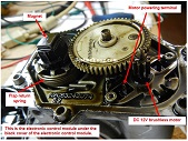
So we have one direction communication from the accelerator pedal to the ECU and two-way communication between the ECU and the throttle body. The accelerator pedal is actually a big and robust potentiometer. And here is how the exactly throttle body with the control unit:
These are the main parts.
The most major problems why the throttle body is in a bad condition:
– Dirt in the throttle body and the flap can’t move freely.
– Brocken parts like a broken spring or failed / broken gear
– Bad control unit
– Bad electro motor
The spring:
The spring is use to move back the flap to its initial point. If the accelerator pedal is pressed then the motor has to overcome the power of the spring and moves the flap in a desired position what is initialized by the ECU.
The magnet:
The magnet is actually in a relation with a hall sensor which is integrated into the black housing and no way to repair or to come close to it. It is used to tell the ECU where the flap is until operation condition.
The motor:
The motor is used to move the flap to a desired position or angle what is requested by the ECU in relation to the position of the accelerator pedal.
The motor is actually a 12v DC brushless component. This motor has no minus or plus terminal because it can be moved in two direction, left and right, whatever is needed.
The big white gear:
The big white gear is connected to the flap and moves the flap when the motor is activated. There is also a black half gear under the white gear. This black half gear is used to move the magnet so the hall sensor can read the position of the flap and send it to the ECU.
The diagram part:
On the J623 you can see the T60/41 or T60/34 or T60/49 this means the 60pin connector where the wiring is exactly on the 41 or 34 or 49 pin on the ECU side.
So, if you disconnect the T60 connector from the ECU and the T5 connector from the throttle body you can check for continuity the wiring between the throttle body and the ECU.
Diagnostic part:
Testing the signals from the ECU:
Check if reference voltage +5V are coming from the ECU with a voltmeter between pin 1 and 3 on the T5 connector.
Check with scope between pin 4 and 5 is there a signal of 12V or a PWM signal from the ECU for a short time ( around 5sec ) until somebody torn on the car but not crank.
Testing the hall sensor part:
Connect to pin 1 +5V and to pin 3 GND.
Connect a voltmeter positive lead to pin 2 and the negative lead to pin 3.
When the flap is open you should read a voltage around 4.5-5V.
If you move by finger the flap to a closing position, your reading should fall almost to 0V when the flap is reached the full closed position.
If you don’t have this kind of reading then you have a hall sensor problem.
I think this is not repairable because the whole electronic is integrated into the black cover of the control module. The only option to repair this kind of problem is to change the cover from a donor throttle body the exactly same type.
Testing the motor:
As this motor is a DC 12V brushless motor, and the terminals are directly connected to the ECU and have nothing to do with the hall sensor electronic in the throttle body electronic control module, I decided to directly power from my lab power source.
My setup on the lab power source was U=12v @ Imax=1.5A.
The flap should start to moving, but no noise or any other sounds come out and the flap also didn’t moved. So I decide to open the unit and inspect it from the inner side.
WARNING!
IF YOU DECIDE TO REMOVE THE BLACK COVER, PLEASE BE CAREFUL BECAUSE THE COVER IS FILLED WITH OIL!
Removed the motor and tried to reverse the polarity but also no current consumption was detectable on my lab power source and no motor movement too. Actually this motor is dead.
When I pushed the terminals on the motor in several directions until the motor was under power, sometime there was some sign of a starting condition but almost for a short time and low power.
Actually, I think the problem was a broken terminal inside the motor. I took out another motor from another throttle body whit the same characteristic and put it into this throttle body and fired up all that stuff and the flap was moving as it should move.
All reference reading from the hall sensor was in a reasonable limits and the throttle body was sent back to the garage. After a few hours I got a call from the garage does the car is repaired and the throttle body repairing was successful.
I hope you enjoy this tutorial and will save lot of repair time.
This article was prepared for you by Christian Robert Adzic from Novi Knezevac-Serbia.
Please give a support by clicking on the social buttons below. Your feedback on the post is welcome. Please leave it in the comments.
P.S- If you enjoyed reading this, click here to subscribe to my blog (free subscription). That way, you’ll never miss a post. You can also forward this website link to your friends and colleagues-thanks!
Note: You can check his previous post in the below link:
https://jestineyong.com/samtec-active-sound-speaker-repair/
 (117)Dislikes
 (0)
(0)
24 Comments
Leave a Reply
Cancel reply


PARASURAMAN
November 28, 2016 at 8:42 am
Good job! Your 'electronic' knowledge of Automobiles, is inimitable! Hat's off!
Robert Calk
November 28, 2016 at 11:06 am
Good job, Christian. Thanks for sharing the repair with us.
David
November 7, 2019 at 9:52 pm
Hi Christian,
Your ECU repair article is very impressive.
May I ask if you have repaired any RST (Roof Soft Top) controller for Mercedes benz? I just got 3 pieces to fix. However, I am lack of technical information for these stuffs. Maybe you are able to help me out a bit.
I am located in Austria, not far away from Graz.
If you need more information or pictures, please let me know.
Regards
david
Mark
November 28, 2016 at 11:34 am
Hey Christian,
Excellent article! I am teaching this subject at the moment and I must admit I haven't seen any filled with oil. Generally we don't see Hall Effect Sensors in the Throttle Bodies.
The type I have dealt with here in Australia, uses redundant potentiometers within the throttle body. These work in opposition to one another (still using a 5 volt reference) and if any readings are not within parameters, the vehicle will go into 'limp home' mode.
The electronic pedal position sensor uses 2 potentiometers again, but this time a resistor is introduced into one of them so that the readings are linear, but different from one another. Of course, one of the problems is that potentiometers have a habit of wearing out their resistive tracks and fail. I guess that's probably why they switched to Hall Effect Sensors.
2 separate 5 volt references are used for the Pedal Position Sensor, however only 1 is used for the Electronic Throttle Body.
Here is a link to what we commonly see here.
http://www.volkspage.net/technik/ssp/ssp/SSP_210.pdf
Once again, I thoroughly enjoy your articles.
Thanks
Mark
Chris
November 28, 2016 at 5:02 pm
Thank you Mark for that informative link. I never saw a TB. that type here in Europe what you described.
The automotive industry is a so complicated think I would say, the same car but for different continent and so much difference.
Here in Europe the most problem with our type of TB are broken spring or broken gears.
I appreciate your interest on my article.
My best regards.
Torosyan
November 28, 2016 at 12:52 pm
You can cut the cover and open the hall sensor. Its repairable.
Chris
November 28, 2016 at 5:03 pm
Thank you for this info.
I didn't try to do that operation but I will the next time I got a hall
problem TB this type.
My best regards.
suranga Electronics
November 28, 2016 at 1:32 pm
Mr- Christian,
Very Good. I haven't seen before this type of repair. Thanks for sharing it.
Yogesh Panchal
November 28, 2016 at 3:07 pm
Christian Robert,
Thanks for sharing new horizon information .
Paris Azis
November 28, 2016 at 4:03 pm
Good job Christian. Thanks for sharing the repair experience.
Marko
November 28, 2016 at 5:14 pm
Mr. Adzic:
A nice piece of work. I look forward to when I can read something that someone had left their effort and passion.
Albert van Bemmelen
November 28, 2016 at 6:12 pm
Very informative repair Christian Robert! And well written. I never repair on Cars and I never owned one either. I do have a driver license for over 26 years now. But I hate Parking and to much grease and combustion engine exhaust gases
for my taste (LOL). But if I ever do your articles on these subjects are surely very helpful.
Andrew F. ali
November 28, 2016 at 8:38 pm
This is one of the BEST repair I ever read...I really learned a lot from you...Thanks a lot
MUSTAFA HAKAN ÜNLÜ
November 28, 2016 at 10:50 pm
Hi,you are professional,where did you get the schematic?
Chris
November 30, 2016 at 7:04 pm
Hi!
Thanks for your compliment, I appreciate that.
The schematic I use is from ElsaWin software.
It Is a big and robust application and server
for the VAG group of cars.
My best regards.
Humberto
November 29, 2016 at 12:48 am
Thanks for such a great tutorial. Keep on.
Bulent NUR
November 29, 2016 at 3:42 am
Thanks for sharing, very informative. Greeting of Turkey.
Henrique Jorge Guimarães Ulbrich
November 29, 2016 at 4:14 am
Dear Christian, thanks for the very didactic explanation. I am fond of cars, and as I dealt all my life with electronics, of course electronic injection systems is of concern. At least, up to the moment that electric cars finally become a reality.
Alvaro Rivillas.
November 29, 2016 at 12:17 pm
very good job Mr Christian . I liked ,congratulations.
moshe
November 29, 2016 at 1:17 pm
Christian...
thank you.
a thoroughly fascinating article and an insight into what happens in various parts of the world with repairing the overcomplex components that cost a small fortune to replace.
Have you ever tried to repair a mass-airflow-meter by any chance?
Chris
November 30, 2016 at 7:01 pm
Hi Moshe, no, I never repaired a MAF sensor but if one will arrive to my service
I will give a try. 🙂
Thank's for supporting my article.
My best regards.
Angelo
December 2, 2016 at 7:54 am
Dear sir(s)
i'm looking for a substitute of cap 220v 330uf for pc power supply..
could someone plz
help me in this regard?
Thank you
durak bilgeoglu
January 4, 2018 at 4:04 pm
hellow i m from turkey i wont learn potantiometer repair i nead you help
David
November 11, 2019 at 5:18 am
Hi Christian,
Your ECU repair article is very impressive.
May I ask if you have repaired any RST (Roof Soft Top) controller for Mercedes benz? I just got 3 pieces to fix. However, I am lack of technical information for these stuffs. Maybe you are able to help me out a bit.
I am located in Austria, not far away from Graz.
If you need more information or pictures, please let me know.
Regards
david