
About Varactor Diodes
They are small, very small and often embedded into Integrated Circuits. Varactor Diodes, also called Varicaps, are used in many of today’s electronic circuits, mainly in RF tuners, oscillators and filters. As electronic repairers you will rarely come across one of them. They are not the type of component that fails often, although some papers suggest that their characteristics might degrade with time.
I needed to use a couple of varicaps for a project; I knew about their existence but never had to deal with them until today. They are quite fascinating devices, principally because they are representative of the huge advancements in miniaturization achieved during these past years. Mobile phones, remote controlled TV, digital radio receivers etc… would not be possible without them. So I wanted to share my discoveries.
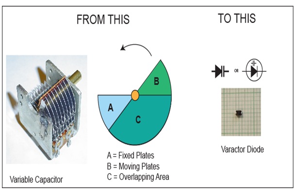
If you ever opened your grandpa’s radio set (if not, you should, but you might wait until he is sleeping!) you will have seen that big mechanical component, a variable capacitor. It looks like some kind of onion slicer… and used to allow the manual tuning of RF resonant circuits, oscillators and filters, in changing the capacitance by turning a knob. You will not find any of those in modern radio sets; they have been replaced by the tiny varactor diodes. Let’s see how this works…
We remember that a capacitor is made of two or more conductive plates separated by an insulating material (called dielectric). The capacitance depends on the thickness and the type of dielectric, and of the area of the facing plates. The larger the area of the facing plates is the larger is the capacitance. The thinner the dielectric is the larger is the capacitance.
Variable Capacitors
Variable capacitors were made of two sets of semicircular blades, insulated from each other. One set of blades is fixed while the other rotates. The rotating blades are inserted between the fixed blades, without touching them, thus forming a capacitor, or more precisely several capacitors in parallel.
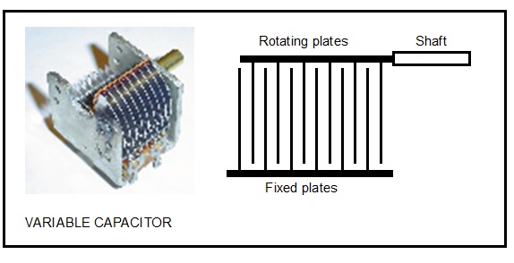
The dielectric is the air separating the plates. By turning the shaft the overlapping area changes (see figure below), thus changing the capacitance. Variable capacitors were widely used in radio sets to manually tune over a range of frequencies. Some designers used variable inductors for the same tuning purpose but they were not as popular as the variable capacitors. Those capacitors were beautiful devices; however they were doomed to disappear because of their size and cost. And they did disappear (almost), replaced with the Varactor Diodes.
Varactor Diodes / Varicaps
Varicaps are based on the fact that a reverse polarized PN junction presents a certain amount of capacitance. And this capacitance changes in function of the reverse voltage applied; the higher the voltage, the smaller the capacitance.
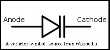
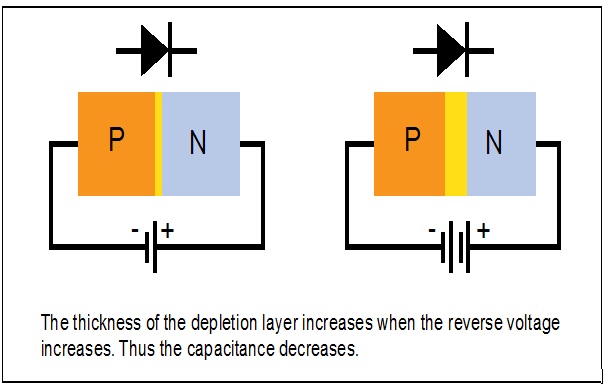
When you apply a reverse voltage (Cathode + and Anode -) across a diode it creates a depletion region, between the P and N regions. The depletion region doesn’t have majority carriers, hence behaves as an insulating dielectric. This is why diodes do not conduct in reverse bias mode. So here we are, a P and N conductive regions, separated by an insulator. This is a capacitor!
When we increase the reverse voltage, the depletion region increases; thus reducing the capacitance. This is how Varactor Diodes work!
Standard diodes, rectifiers, transistor PN junctions (base – emitter) present this characteristic, which is considered as a nuisance, mainly in HF and fast switching circuits. Therefore semiconductor manufacturers try to minimize the capacitance. In the case of Varicaps, however, this capacitance is a blessing and they try to make it as large as possible. This is, as far as I know, the main difference.
Measuring Varactor Diodes
As far as a Go/No-go test is concerned, varactor diodes can be tested like any standard diode. They conduct in one direction showing a voltage drop of around 0.6 V and do not conduct in the other direction. For my project I bought a few BB148. I needed only two of them but I bought 20 pieces because they are cheap and they tend to jump out of the tweezers and disappear forever! I was keen to measure the capacitance for various voltages. Not that I do not trust the manufacturer’s specifications, but by pure curiosity. For this we need to add a few components as follows:
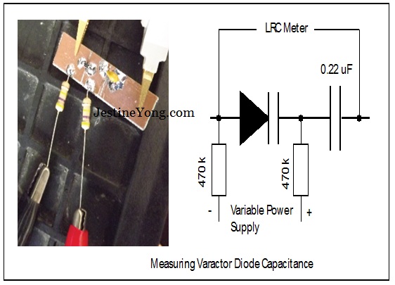
The 0.22 uF capacitor blocks the DC so it will not upset the LRC meter and the two 470 K resistors are high enough for the power supply impedance not to affect the measurement. As the current is very low (reverse bias!) the voltage drop will be negligible. Here are the measurements:
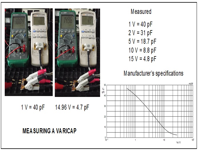
This is pretty good; it matches exactly the manufacturer’s specifications.
The next step now is to understand how they fit in a resonant circuit? We cannot simply replace the capacitor with a varicap. There are a couple of ways of doing it:
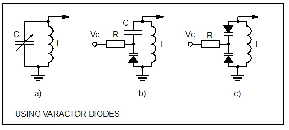
The figure above shows how to replace a variable capacitor (Circuit a) with a varicap (Circuit b). The capacitor C prevents the DC from the control voltage (Vc) from being shorted by the inductor L. It should be 10x or more the value of the varicap in order not to interfere in the resonance frequency. The resistor will be 100 k or more to insulate the voltage source. One problem with this design is that the AC from the resonant circuit might forward bias the varactor diode during half periods thus creating a distortion. To avoid this we can use a second varactor diode (circuit c). This is the preferred method; however the variable capacitance will only be half of the Varicap value (like two capacitors in series). Well, nothing is perfect!
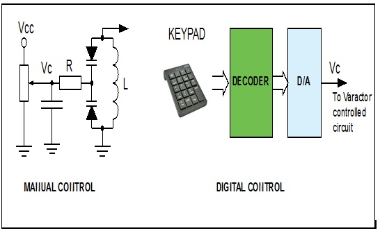
The beauty of this is that the control voltage (Vc) can be generated from different kind of sources. Either with a potentiometer for a manual tuning or by any type of electronic circuits such as microcontrollers using Digital to Analog (D/A) circuitry etc…
Back to my project I built a small RF oscillator using a potentiometer to control the frequency. .. Indeed I also used a second potentiometer (in series with the main one) to allow for fine tuning. The main potentiometer value is 100 k while the second potentiometer value is 10 k.
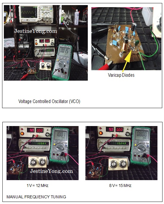
Here we go; the old bulky and expensive variable capacitor is no longer needed!
As mentioned earlier, any PN junction presents this variable capacitance characteristic when reverse biased. Some hobbyist use conventional diodes or even LEDs. Some diodes present very similar characteristics to the Varicap used in this project; I did some testings using standard LEDs as Varicaps and it works quite well! The main problem is that there is no consistency between two diodes of the same type because they are not designed for this purpose. It’s OK for hobby projects but not for industrial applications.
What’s next?
Despite their huge advantage, Varactor Diodes are not the ideal components yet, as they suffer from a number of problems, including a limited tuning range. New components, called MEMS Varactors (Micro Electro Mechanical Systems) are emerging and will, one day, totally replace the Varicaps.
In the meantime, we can have have fun with this wonderful component.

This article was contributed by Gerald Musy from Penang, Malaysia.
Please give a support by clicking on the social buttons below. Your feedback on the post is welcome. Please leave it in the comments.
P.S- Do you know of any your friends who would benefit from this content that you are reading now? If so, forward this website to your friends or you can invite your friends to subscribe to my newsletter for free in this Link.
You may check out his previous article about USB charger:
https://www.jestineyong.com/the-mystery-of-usb-chargers/
 (196)Dislikes
 (1)
(1)
32 Comments
Leave a Reply
Cancel reply


curt
September 2, 2014 at 12:57 pm
thank you for the info ,
Rudi Wijaya
September 2, 2014 at 3:19 pm
Wow, great information ! Thank you sir !
Martin
September 2, 2014 at 4:26 pm
Fascinating! I really enjoyed this article. Thank you.
Venu gopal
September 2, 2014 at 5:26 pm
Useful info and nice presentation. Thank you. !
john
September 2, 2014 at 6:18 pm
V nice thanks a lot
Dominic
September 2, 2014 at 6:33 pm
Wow!! What an article....verrry informative!!You always know they're in the tuner part of a circuit but they're usually sight unseen since they almost never cause trouble.But your article highlights how much even experienced technicians don't know about them!
Anwar Shiekh
September 2, 2014 at 8:07 pm
I recently looked inside a garage opener transmitter, and there was a small variable capacitor to tune the frequency; quite annoying as I would have preferred they use a crystal.
Gerald
September 3, 2014 at 11:05 am
Hi Anwar, thanks for your comments. You are right, we should not use variable tuning in those devices. Too easy to get out of tune.
Cheers,
GM
Alan
September 2, 2014 at 8:15 pm
I made a video on this topic earlier this year:
https://www.youtube.com/watch?v=icw8terKP-M
Robert
September 3, 2014 at 12:15 am
Hi Alan. You have a lot of great videos, that's why I'm a subscriber. Thanks.
Gerald
September 3, 2014 at 11:01 am
Hi Alan,
Thanks for the link; Very nice video indeed. On that page I came across a few more of your videos, great tutorials. I like the one on your call sign... I used to be HB9AJD, then YB1AEG then PY6ZAP. But nothing here in Malaysia. Like to start again but not sure if it is worthwhile, seems there is no one anymore on the SW?
73's GM
Henrique Ulbrich
September 2, 2014 at 8:32 pm
Very didactic, clear information. Congratulations and many thanks
Mark Tembo
September 2, 2014 at 9:25 pm
I have enjoyed this information. Thanks a lot!
alberto
September 2, 2014 at 9:47 pm
Excellent presentation, thank you very much.
Merlin Marquardt
September 2, 2014 at 11:54 pm
Very informative. Well done.
Robert
September 3, 2014 at 12:00 am
Thanks Gerald. Very interesting.
Jumbe Mateyu
September 3, 2014 at 2:46 am
As a broadcast engineer, I enjoyed reading it infact I have learnt something from your article.Thank you very much Gerald.
mahmoud
September 3, 2014 at 3:57 am
dear sir before this I knew that how varicaps work but you teach me very very excellent.thanks alot
Tyrone
September 3, 2014 at 4:27 am
Very good information thank you.
Imraz
September 3, 2014 at 5:09 am
Hi Gerald Musy
I really liked this very informative article. As you said varicaps are very reliable and doesn't burn out easily that why its not vastly covered in electronic repairing but the easy to understand information you gave is outstanding.
Thanks and keep the articles flowing.
Andre Gopee
September 3, 2014 at 9:51 am
Great article.... Alan Your article I understood even better. Thank you both for sharing.
Yogesh Panchal
September 3, 2014 at 11:09 am
Informative ! thanks for sharing.
Muhammad AKhlaq
September 3, 2014 at 1:44 pm
A very much ellaborative and well narrated artical.
Humberto
September 3, 2014 at 6:22 pm
An instructive article, as usual. Thanks and congratulations.
Capt36
September 4, 2014 at 12:31 am
I love it when I learn.!
Excellent article!
Thanks for the fun of learning!
Clair
September 4, 2014 at 12:46 am
I have a Motorola data book from the 80's and they claim that you can use zener diodes as varactor diodes, depending on the wattage of zener diode that is used they can have capacitances into the 1,000 pf range!
felipe paco
September 4, 2014 at 8:43 am
great thanks for sharing the data.
Gerald
September 5, 2014 at 2:06 pm
Thank you everyone for your comments.
Cheers,
GM
Taofiki ishola Akinleye
September 6, 2014 at 7:34 pm
Thanks very much is very enjoyable God bless you.
Raymundo Saura
September 7, 2014 at 10:05 am
thanks sir
bidebi
September 18, 2014 at 10:58 pm
I would like to say thanks to you for all the information that you provide us for repair, if you are member how you can get those books
or copy them ? thank you
Dan
November 8, 2014 at 10:01 am
thank you that is a good article thanks for sharing