
ABW Multimeter Blown Apart
It’s easy to get it wrong. Sometimes, VERY wrong. That’s what happened to me when I filmed my very first YouTube video for my new channel. I was repairing a microwave oven and not realising the high voltages that they have, decided to test the high voltage transformer with my CAT2 rated multimeter.

To say things didn’t go according to plan is an understatement. There was a puff of smoke from my meter and after that it decided to just provide me with gibberish on the screen. Let me set the record straight – it was not the fault of the meter, it was user error. I was very upset as I had had this multimeter for many years and had just introduced it to the world of electronics, but it didn’t seem as excited as I was. I can now understand why……..
I did open up the back several times and was left with a blank expression on my face as I saw all the coloured components that refused to operate as they should. It went into the ‘too hard basket’. Step forward 5 years.
Now, I’m the first person to stick up my hand and tell you that I don’t know everything and am always keen to listen to others to guide me on my constant quest for knowledge. That being said, after all these years had passed, I had added to my knowledge base and surprised myself on many occasions with a successful repair.
The main thing to remember is – don’t get cocky. You can always learn something from others and just when you least expect it, you have forgotten some of the basics! Anyway, enough of that, I need to get back to my multimeter repair.
I had recently carried out a simple repair on a multimeter where someone (one of my students) had incorrectly replaced one of the sliding switches on the rotary dial and this had made the multimeter inoperable. Armed with this small success, I decided to have a look at several other multimeters that I had in my collection that didn’t work. The one that we are discussing, as well as several others that had been given to me by others that also did not work. (Stay tuned for further repairs)
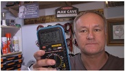
The first thing I noticed about this ABW multimeter (which is identical to several other brands), was that the display worked. The main problem was that all the numbers, icons and features came up together, regardless of what position you had the rotary dial on.
That let me to thinking that firstly, the fuse was OK and the display was also working. It seemed to be some sort of processing issue.
Of course, the first thing to do in any diagnostic situation is to have a very good visual. I inspected the board and components carefully to look for dry solder joints, damaged components or evidence that the magic smoke had disappeared. Everything seemed OK, but I knew better!
I started a systematic testing of diodes, transistors and resistors. Nothing out of the ordinary. Time to raise the game. IC’s were next. For many years these little black boxes with legs resembling caterpillars mesmerised me and I felt that I had no right looking in their direction. Today was different! I had recently successfully repaired several units replacing faulty IC’s and was quietly gaining confidence in my chosen hobby.
I’ll be honest here – I have several of the same meter and so testing and comparing meter against meter showed a definite difference in readings. This led me to isolating the fault.
After waiting for some time to receive the items through the post, I went about carrying out the soldering process. I have replaced quite a few SMD’s with success and found the best way to replace these IC’s was to flood the area with solder and then heating that big blob would release all the IC’s legs at once.
I have now been introduced to a recently purchased hot air station and have been practicing removing components with hot air. This is another skill I have been able to learn.
The first IC to be replaced was a 27M2C OpAmp, which installed nicely. This gave me some practice to tackle the larger CD4053BM Multiplexer. After preparing the pads for new solder and adding flux, I carefully placed the tiny IC’s in position. Soldering one leg in place gave me the opportunity to realign them before completing the soldering.
At this point, I decided to test the operation of the multimeter and to my surprise, it worked! Not to be too sure of myself, I checked the operation of all the features and compared the readings with my good multimeter. They all checked out and were very close to the other meter’s readings. I even checked the frequency and duty cycle readings using a function generator I had made previously.
To say that I was impressed with the results was an understatement and it gave me a boost to my confidence and newly acquired diagnostic and repair skills.
The multimeter would live to measure another day! If you are interested in this repair, you can see a video on my channel following the link below.
This article was prepared for you by Mark Rabone from Australia.
Please give a support by clicking on the social buttons below. Your feedback on the post is welcome. Please leave it in the comments.
P.S- Do you know of any your friends who would benefit from this content that you are reading now? If so, forward this website to your friends or you can invite your friends to subscribe to my newsletter for free in this Link.
Note: You can check out his previous repair article below: https://jestineyong.com/troubleshooting-and-repairing-benq-lcd-monitor-with-video/
 (74)Dislikes
 (1)
(1)
22 Comments
Leave a Reply
Cancel reply


Parasuraman S
June 27, 2020 at 8:30 pm
Rightfully matching your name, we all should 'mark' this article for future reference! A great lot of 'pump-up' and cheer-up advice and statements! All from true experiences! Well, I have run out of words to express my admiration! Hat's off! This gives me confidence to rectify a problem that I have with my Fluke 15B+, which I accidently used to measure 230V AC in auto ohms range! It is working well, but some readings in the order of Megs keep running though when we connect it to a resistor, it shows correct reading. So, looks like the 'central nut' (as we say about human beings) has gone lose! I look forward to your guidance on this! Many thanks for your wonderful and very useful article!
Mark
June 27, 2020 at 10:38 pm
Hey Parasuraman,
Thanks for your kind comments. As I said, I am learning all the time and take on new projects to test my skill level. Sometimes successfully, other times, not so much. It is a sad day when our beloved multimeter gets blown up. That's why you have more than one.....or two....or twenty two 🙂
Albert van Bemmelen
June 27, 2020 at 8:32 pm
It is a very good feeling if our defect equipment can be fixed as new!
And you may be surprised if I tell you Mark, that also in VHDL coding/programming the Multiplexer has a very important place. It helps reducing the amount of needed 'virtual' VHDL coded components in a circuit. So apparently it also serves as a very important component to reduce complex functions in our DMM!
Mark
June 27, 2020 at 10:43 pm
Hey Albert,
That's interesting! I don't know too much about the inner workings of a multimeter, but was able to identify and replace the faulty components.
What do you think the role of the Multiplexer would be in the Multimeter?
Henrique J. G. Ulbrich
June 27, 2020 at 11:48 pm
I have an old Sanwa digital multitester that was also destroyed by a wrong measure. It is set aside for many, many years. In the same way as Parasuraman, your article gave me the inspiration for trying to fix it. Thanks for sharing.
Mark
June 28, 2020 at 11:04 am
Hey Henrique,
I felt exactly the same and believe me I am no electronics genius, just a guy learning from others, like the many talented people on this site. I have gained a lot of skills that I thought I'd never learn, but realise that I will not always succeed. The main thing is to take it slow, think simply and logically. I carefully checked all the passive components and then thought the only things left that made sense were the IC's.
It's scary but exciting stuff, especially the very first time diagnosing and replacing those tiny little SMD's.
Good luck on your repair!
Don Oser
June 28, 2020 at 2:15 am
Mark, great repair! I to have a to hard to repair shelf. Just like you I slowly repair these devises as my skills improve. A multimeter is like family member to me. Haven’t blown mine yet.
Mark
June 28, 2020 at 11:10 am
Hey Don,
Congratulations on not blowing up your multimeter! You are right, they do become like family (what a weird bunch we are!) 🙂
I teach a multimeter subject in the classes I offer at the college where I work part time.
I intend to make a multimeter series of videos on my YouTube channel.
You sound like me with a shelf set aside for when my skills improve.
Well done!
Albert van Bemmelen
June 28, 2020 at 5:11 am
Hi Mark. In case we take as example the 4053 mux (mux is short for Multiplexer), it is a tripple single-pole double-throw analog switch. So it is able to switch 3 different analogue switches depending on the value at each of the selectors S1, S2 and S3. And each S selector is selectable to output Y0 or Y1. Where Z is its input. Or vice versa where inputs are Y0 or Y1, and Z is its output. So it exists out 3 bi-directional independent (analogue) switches. If you look at the datasheet that means that we have pin 14, pin 15 and 4 as P-contact of each of the 3 double throw switches. And they are switched by respectively pins 11,10 and 9. Which means that pin 14 is able to switch between pins 12 and 13. Pin 15 between pins 2 and 1. And P-contact pin 4 between pin 5 and 3. If selector pins 11, 10 and 9 are 1/3 Vdd the pins 12 , 2 or 5 are chosen. If selector pins 11, 10 and 9 are 2/3 Vdd pins 13, 1 and 3 are selected. Each switch works completely independent of the position of the other 2 switches in the 4053. So a very interesting multiplexer also useable for Audio uses or maybe even as Video input selector. What it does in the DMM is now easy traceable if you look at how the 3 switches are connected in your meter.
Albert van Bemmelen
June 28, 2020 at 7:57 am
By-the-way: The CD4053 can be used for analogue as well as for digital multiplex or de-multiplex purposes. Depending on the signal direction. For
operation as a digital multiplexer/demultiplexer, VEE is connected to VSS (typically ground). If Y0 and Y1 of every switch are used as (digital) inputs and Z as output it is a mux and S is its (digital 0 or 1 => 1 bit so 2 possibilities Y0 or Y1) selector input. In that case it is a 2 to 1 multiplexer. In the other signal direction it is a demultiplexer or simple decoder. Only in case all 3 switches were used and only shared a single output it would have been a 6 to 1 multiplexer but now it is likely just a 3 times 2x1 multiplexer/de-multiplexer. And it would have had 3 selection lines S0 to S2 (to be able to select all 6 inputs individually to 1 output => 6 positions = 000 to 110 binary).
Or to make it more difficult: A Decoder decodes an encrypted input signal to multiple output signals from one format to another format. A De-Multiplexer routes an input signal to multiple output signals. A Decoder has 'n' input lines and maximum of 2n output lines. A De-Multiplexer has single input, 'n' selection lines and maximum of 2n outputs. Or DEMUX is used when the circuit wishes to send the data signal to one of the many devices. A decoder is used to select among many devices.
Mark
June 28, 2020 at 2:23 pm
Hey Albert,
Perhaps they should have named it a 'multicomplexer'! 🙂
I am only learning about the complexity of IC systems, but find it fascinating.
Thanks for the extra information.
Mark
June 28, 2020 at 11:15 am
Hey Albert,
Thanks for explaining that to me - it was very interesting. So I guess in layman's terms, it could almost be classified as a multiswitch working thru a bank of relays.
I will pull apart my multimeter (or at least ONE of them - there's so many to choose from ) and see if I can trace where the switches go to.
Thanks again for getting back to me
Albert van Bemmelen
June 29, 2020 at 8:45 pm
No problem Mark. I hope you'll discover what its function is in your DMM. And maybe write about in your next DMM repair? About the mentioned 6 to 1 Mux, it would only need 6 different selection values to address any of the six inputs individually. So to be exact we only need the 6 values 000,001,010,011,100,101.
Because although 110 is 6 decimal it already would be the seventh selection value counting from 000 that is not needed. Or if '000'is used for instance as Reset or Z output activation (Z impedance,so not low or high neither, ideal for connecting to heavily occupied databus traffic) then all 7 values 000 upto to 110 binary would be used. Cheers!
moshe
June 28, 2020 at 7:06 am
now THAT was a great article!
Mark
June 28, 2020 at 11:16 am
Hey Moshe,
Thanks
I'm glad you got something from it.
John Kent
June 29, 2020 at 1:52 am
I admire your capacity for trying something. I have destroyed numerous meters in the past and thought... Do I need to repair this or replace. NowI am older I repair rather than throw away.
Good work.
Mark
June 30, 2020 at 7:08 am
Hey John,
That's great news. Age does have it's advantages at times.
Instead of getting into something that we think we should be able to do, it's good to realise our limitations, understand that we don't know everything, listen to advice from others and then slowly increase our knowledge to a level that we feel comfortable taking on a new project.
That takes time and wisdom, something I would gladly tell my 'younger self'. 🙂
Humberto
June 30, 2020 at 10:33 am
Well-done Mark
Mark
July 1, 2020 at 6:44 am
Thanks Humberto
Raj
August 5, 2020 at 9:20 pm
Great Sharing.. Cheers.
cipriano olivar
August 14, 2020 at 6:57 pm
excelente,muchas gracias
============================
excellent thank you very much
Zachary
October 8, 2023 at 1:09 am
Greetings, I recently made the same mistake on my es585 haha (tested a bug zapper that I misread the joules as volts xD. I have now found that my 27m2c is heating up and likely fried as I get no input on the screen or beeps. I was wondering, did you buy a replacement for it? If so which, as I cannot find the exact one for the life of me, the closest I found is this but my unit uses a 27m2c 96m a3n7 which doesn't match any online listings. I look forward to your reply.
Regards,
Zachary.