
ATX PSU Modified Into a Car Battery Charger-Part 2
Click HERE to go to part 1
After thinking of all these parameters over again, I took in hand my good old Motorola manual (Linear/Switchmode Voltage Regulator manual, 1982 edition), located the TL494 IC data sheet and started working first with pencil and paper, trying to analyze the original design, in order to modify it later and bring it to the shape I needed.
Well, I will not enter here a boring for many readers mathematical analysis, but I will give you the basic information about what I did with it and first of all I think that some basic theory is important for a better understanding of the topic.
These PWM controllers (as their shortcut name implies, meaning Pulse Width Modulation) control the magnitude of the output voltage of a PSU by controlling the width of each pulse within the pulse train they produce at their output. This function breaks the rectified DC input voltage in pulses and the following width control of them corresponds finally to corrections the PW modulator does against any variations of the output voltage from its predetermined voltage level. These variations can be due either to load changes at the PSU output or to input (mains) voltage variations.
Voltage control is achieved by comparison of a sawtooth shaped, high frequency oscillatory signal, with a DC feedback voltage within an op amp. The op amp is working as a voltage comparator. The DC feedback voltage is a fragment (sample) of the output voltage of the PSU. If this voltage tends for any reason to decrease, the pulse width increases instantly and accordingly, in order to correct the output, bringing it to the predetermined level. This works vice-versa.
Current control is achieved in a similar manner. This time a second op amp is used, working as voltage comparator again. It compares a varying DC voltage feedback, with a stable DC reference voltage. The magnitude of the feedback voltage represents the magnitude of the output current of the PSU. Therefore it’s a load dependent voltage. The stable DC reference voltage on the other hand, represents the maximum permissible output current. As long as the output current is lower than the maximum permissible value, the output of the op amp remains zero volts and vice versa. The transformation of the output current in voltage is easily achieved by using a sub-Ohm current sensing resistor, connected in series with the DC output of the PSU.
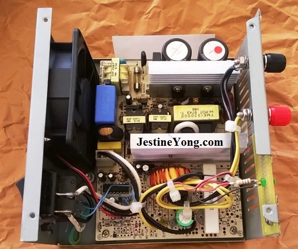
Both of these op amps, along with the independent PWM comparator, are included in the TL494 and finally they control the PWM modulator, also included therein. Originally only one of them was used, regulating the output voltages. So I made the proper modifications in the PCB foil traces and employed the second op amp as well. After calculating the new resistor values of the feedback resistive divider for the voltage regulator, I inserted them in the empty places of the original resistors and drew a pair of thin cables for the voltage selector switch. These are the blue colored cables shown in the above photo. I also exploited a mains voltage selector switch (115/220V) which already was available. These two thin blue cables go directly to its terminals. Its 115V indication means now 13,2V DC at the output, whereas its 220V indication means boost charging voltage of 14,7V DC at the output.
All this switch does is to short out an additional (third) resistor which I connected in series with the first one one of the upper side of the resistive divider. This in turn results in 13,2V DC at the output. For boost charging voltage at the output the switch is thrown to its open contacts (220V) position. This action removes the previous short, the voltage at the divider’s node drops and this finally forces the output voltage to jump to 14,7V DC.
For the current limit circuit I used a 0,1Ω resistor (the big white one shown in the photo of the PCB in its final form) and worked applying Ohms Law once again. I set the maximum permissible current output level to six amps. This means 600mV stable reference at the current comparator. I chose this amperage just for safety, considering that the original rectifier diode was rated 10A. This amperage is enough for a decent car battery charger and for batteries up to 100Ah.
At the end I also replaced that current sensing resistor with one of higher wattage. I put there a 10W resistor instead of the 5W one, again for reliability reasons alone. The power consumption of it was calculated at 3,6W and the 5W resistor I originally had put there was getting remarkably heated when the PSU was working under current limit conditions. (This will be a normal condition from now on during the first (bulk) stage of the charging procedure of a flat battery). Although the wasted energy in form of heat within it, under current limit conditions, will remain unchanged, the upgraded replacement has nevertheless better thermal distribution on its (bigger) body and of course can tolerate this power more easily. Practically it works much cooler than its 5W counterpart under current limit conditions.
For the same (safety) reason I replaced the output filter capacitor with another one having kept the original capacitance but upgraded voltage rating. The original was a 1000μF/16V, but due to the increase of the output voltage after the modification it was working marginally, that is, very near to its nominal voltage. So I replaced it with another one keeping the same capacitance but upgrading its working voltage to 25V. The one with the green color shown in the modified PCB is the new replacement cap.
Finally I also changed the power supply connection of the cooling fan.
Originally the fan was supplied from the +12V output supply. After the modification this voltage was increased (ranging from 13,2V to 14,7V) and the cooling fan (which is permanently powered, without a thermostat to control it) was spinning crazily!! So, in order to protect it as much as possible, I connected it to the auxiliary (standby) +12V supply, which was independently stabilized, produced from the little standby transformer which also feeds the PWM IC from another secondary winding with a higher voltage of 22V. The power consumption of the fan was far below from being considered as dangerous for the tiny standby power supply. An additional advantage of this change, apart from the normal spinning of the fan, is the fact that the fan itself was now a direct indicator that the standby supply is working (no matter that this standby function does not exist any longer, because both main and auxiliary supplies are main switch depended after the modification and this fact is not likely to be changed for the rest of the life of this PSU). However I also connected a green LED in parallel to the fan power connections, for better control of its working state.
This photo below shows its inner side, at its final form.
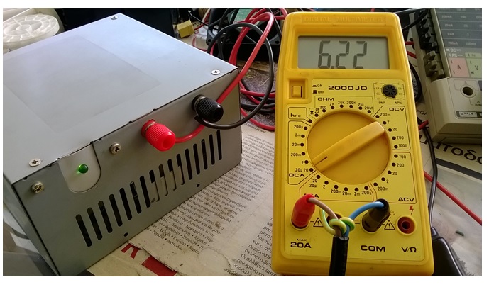
You can see its output voltages below. The small variations are due to the tolerances of the resistors I used.
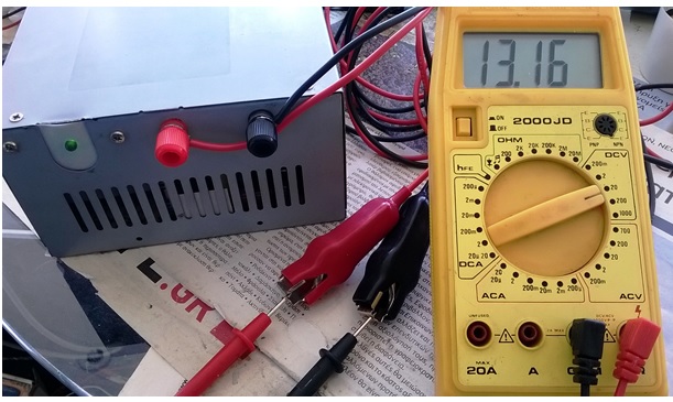
This photo above, is the output with the switch in its 115V position.
And this one below is the output with the switch in its 230V position.
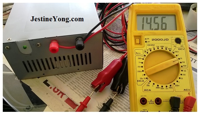
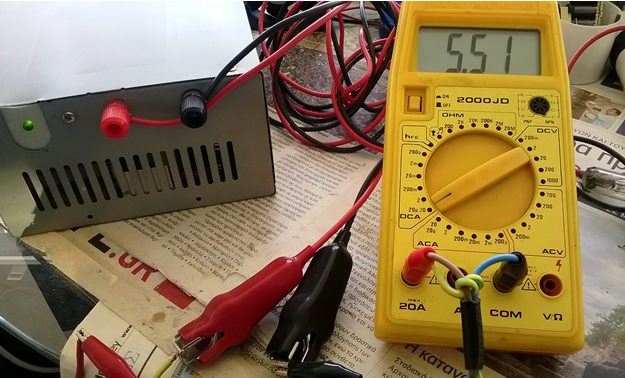
You can also see below the current management of this PSU.
First shown is the short circuit current. It is just a little bit above the calculated 6A maximum, due to the resistors’ tolerances again.
And this below shows the current draw of a 12V/60W rated H4 halogen car head lamp. The filament used for the test is the high beam one.
Normally, in order for me to avoid these variations from the calculated values, I should use metal film resistors of tighter tolerances, say 1%, but I have plenty of carbon film resistors in stock (with 10% tolerances of course) and so I preferred to use these. Anyway the resultant slight variations of the output parameters mean nothing important in this application and I am sure that my brother will forgive me about that!
The only missing protection of this PSU is the one against accidental connection of the battery poles in reverse. I asked my brother if he wanted me to include a relevant additional circuit therein, but he was quite convincing me in that on one hand he didn’t need this protection, while on the other hand he already knew about the results of such a wrong connection and therefore he is cautious enough as regards this matter. Therefore I excluded this protection circuit keeping things as simple as possible.
Talking in terms of reliability, this charger has all those elements which can characterize it as a decent and bulletproof car battery charger, except that “battery in reverse polarity” protection. As functional tests, I short circuited its output about a hundred times repeatedly and additionally I used it to charge some batteries I have here to play with. After all these basic crash tests I informed my brother that he does not need to buy any car battery charger at all. His charger is already here waiting to serve him. And I believe that it will do so both flawlessly and for long time. So I intend to give it to him by the first chance I will visit him.
I believe that (if he inspects its blower for proper function regularly…I made that crystal clear to him) he will be very happy with it, enjoying its services possibly for many years to come!
I also hope that this modification was interesting for you and that you enjoyed this experience as well…

This article was prepared for you by Paris Azis from Athens-Greece. He is 59 years old and has more than 30 years’ experience in electronics repairs, both in consumer and industrial electronics. He started as a hobbyist at the age of 12 years and ended his professional carrier as a senior electronics technician. He has been a specialist in the entire range of consumer electronics repairs (: valve radio and BW TV receivers, transistorized color CRT TV, audio amps, reel and cassette tape recorders, telephone answering and telefax devices, electric irons, MW cooking devices e.t.c) working in his early stages at the official service departments of National-Panasonic first and JVC afterwards, at their premises in Athens.
Then he joined the telecoms industry, working for 20 years as field supporting technician in the sector of DMRs (: Digital Microwave Radio transmission stations), ending his carrier with this subject. Now he is a hobbyist again!
Please give a support by clicking on the social buttons below. Your feedback on the post is welcome. Please leave it in the comments.
P.S- If you enjoyed reading this, click here to subscribe to my blog (free subscription). That way, you’ll never miss a post. You can also forward this website link to your friends and colleagues-thanks!
Note: You can check out his previous repair article below:
https://www.jestineyong.com/netvil-dvb-t-receiver-no-power-on-repair/
 (93)Dislikes
 (1)
(1)
31 Comments
Leave a Reply
Cancel reply


George Greenfield
April 14, 2016 at 6:55 pm
Paris,
Interesting mod. I would never thought of it. Thanks for the article.
George
Paris Azis
April 15, 2016 at 1:21 am
Hey George
Yes, it’s very helpful to use such PSUs either as battery chargers or as bench, fixed voltage PSUs, which is the easier way of using them, without modifications.
Well, depending upon their design, this does not always work. Some of them do not work at all if you draw current only from the 12V output. Then one has to move on with modifications.
In the simplest version one can also remove the cables and install the usual red and black PSU output terminals, like those I installed in mine, with all the outputs available, against the common return.
Greetings
Albert van Bemmelen
April 14, 2016 at 8:11 pm
Very nice article Paris. Especially the over-current protection you
added to the second previous unused TL494 Opamp is just Genius. Next
to the TL494 you explained, also the TL497 used to be a well known IC
in special Power Supply circuits. Quite often chosen in Eprom
Programmers circuits to create the higher Vpp programming voltages for
the with UV light erasable Eproms. And also the famous uA723 (which
had Current limiting but no PWM yet) I used once to create a 15 Amps(!!) completely Short-Current-Proof 13.8Volt Power Supply with 4 extremely
cooled 2N3055 Power Transistors on a big Heatsink. Which of course
generated a lot of heat because its inefficient Linear Regulating.
Luckily todays PWM SMPS made Power Supplies much smaller and less
Energy consuming as is the way to go.
Paris Azis
April 15, 2016 at 1:49 am
Thank you Albert.
Yes, a car battery charger without current limiting protection is very dangerous to be put in operation. During the bulk stage of charging of a flat battery the current will reach enormous levels and the result will be a burned out PSU. The same holds true in case of an output short circuit. The inclusion of this protection was therefore absolutely necessary.
I have also been working a lot with the MC1723 (the Motorola version of μA723). I have used it for my adjustable linear PSU as well, as a voltage reference. Its internal 7,15V reference is still notorious for its stability over time. I produce the basic 10V with it and then manage both voltage and current using this 10V auxiliary supply. My output is 0-20V, 0-5A. My output transistors are two TIP142 Darlingtons in parallel. Just excellent old Motorola versions. Their gain is 2500. (I measured it with real currents flowing through them when I built it). This PSU is practically immortal. I built it 30 years ago and it still works perfectly. I use a relatively small heat-sink in it but I also use an excellent (old again, all aluminium made) Papst blower, working directly with mains supply.
I know that TL497. It is similar, but cannot be used in push pull mode as it has a sinle output. This rather makes it good for step up or step down DC/DC converter applications…
Greetings
sudhir
April 14, 2016 at 8:12 pm
Wow Paris!!
Many thanks for this article. It was really a big task to redesign the circuitry, and can only be done who understand electronics very well and have experience like you have.
It would be great if you just uploaded the recalculated value and circuit design in order to modify this unit.
learned a lot from this articular and wish you all the best for the next.
Thank you
Paris Azis
April 15, 2016 at 1:57 am
Hi Sudhir
Thank you too for your kind words. Yes, redesigning an existing circuitry is not an easy task at all. Anyway I can manage the needed modifications in PSUs as I am long ago familiar with them. But still it’s a difficult task.
I will see what I can do with your request about the component values.
Greetings
Mark
April 14, 2016 at 8:59 pm
Hey Paris,
Congrats on an excellent repair and article. I hope your brother appreciates all the hard work you put in. I'm sure I will be better than most store bought chargers.
Brilliant idea using a ATX PSU SMPS!
Paris Azis
April 15, 2016 at 2:25 am
Hey Mark
Thank you too for your kind words. I am sure that my brother really appreciates that and he already knew he could rely on me about a good charger. Finally he deserves the hard work I put in. Our helping each other is indeed bidirectional.
Talking about reliability of that PSU, believe me that I did what I could in order to burn it before telling him that I had made a charger for him. So it passed all the crash tests successfully.
Hopefully there will not be any sad surprises later on, given that cooling is good and current is limited in a level that the device can tolerate easily. I didn’t violate the original specs of it as well.
Moreover this is not the first time I made this modification…I have a good experience on that…
Greetings
Humberto
April 14, 2016 at 11:46 pm
Hi Paris, good ideas you have had in this innovation with a SMPS of a PC. Congratulations.
Paris Azis
April 15, 2016 at 2:22 pm
Hello Humberto
Please take a look again to my answer to you on your comment of part 1 of the article… Thanks again!
Greetings
Gerald
April 15, 2016 at 8:49 am
Hi Paris
Great article and great modification. There are plenty of cheap battery chargers on the market but this one is of much more value as very cleverly engineered. Also for your brother it will have an additional value as a product of his brother's engineering skills.
Great job, thanks for sharing. Looking forward for more of the same kind.
Cheers,
Gerald
Paris Azis
April 15, 2016 at 2:33 pm
Hello Professor!
Thank you for your inspiring comment. Indeed, a “hand made” gadget, when it is also a “heart made” one, always includes a high dose of added value in it.
The truth is that I wanted to offer my brother something being both simple in its operation and reliable for the purpose he needs it.
My Greetings to you
SAJID RAUF RAJA
April 15, 2016 at 10:54 am
Good Morning Azis,
Congratulations on your successful assignment
Weldone, keep it up for future successful tasks.
Kind regards,
Sajid Rauf Raja.
Paris Azis
April 15, 2016 at 2:36 pm
Good day to you too Sajid
Thank you for your kind words.
Best Regards
Anthony
April 15, 2016 at 11:50 am
Hi Mr Paris Sir,
A very great pleasure to read your always interesting and educational articles here ! Thanks so much for sharing them with us. If secret agent James Bond ever needs a new inventor building gadgets for him, I'm sure you would more than qualify for that role !
Best Regards
Paris Azis
April 15, 2016 at 2:43 pm
Hi Anthony
Thank you for your kind and positive comment. I have never thought about helping in covering James Bonds’ needs…!!
Best Regards
beh
April 15, 2016 at 12:31 pm
Paris :like your other articles this one is very inspiring
thanks & regards
beh
Paris Azis
April 15, 2016 at 2:46 pm
Hi Beh
Thanks for your support.
Best Regards
Robert Calk
April 15, 2016 at 2:28 pm
Nice job, Paris. The articles were a pleasure to read. Thanks.
Paris Azis
April 16, 2016 at 1:01 am
Hi Robert
Thanks a lot for your support.
Greetings
Mohammed kasim C M
April 16, 2016 at 1:34 am
Very interesting to read........
Paris Azis
April 17, 2016 at 2:41 am
Hi Mohammed
Thank you for your support. (I am still trying to build that jig for the article you are waiting for. I have lost the original and the constructions I made up to now tend to oscillate. As soon as I fix this problem the article will be released at once. I didn't forget you)!
Greetings
Parasuraman S
April 16, 2016 at 9:04 am
Well done! I have already commented with my heart out on the first part of this article! I have nothing more to say! Great depth proves to say that an electronics stalwart can do anything and everything! I thank God for bringing me to this forum, from which I am learning many, many things every time! Special thanks to Jestine Yong too!
Paris Azis
April 17, 2016 at 2:43 am
Hello Parasuraman
Thank you for your warm acceptance of this article and your inspiring support.
Best Regards!
Beau
April 16, 2016 at 12:49 pm
Outstanding!!!!
Paris Azis
April 17, 2016 at 2:44 am
Thank you Beau for your positive comment.
Greetings
Henrique Jorge Guimarães Ulbrich
April 17, 2016 at 12:06 am
Great, Paris. This is the solution I was looking for. Indeed, I'll build one for my own use. For this, I need more details, mainly concerning the exact points you did all the connection (or, in other words, a schematic diagram of your work). Would it be possible, please? Anyhow, I'm grateful of this (as always) didactic article. Undoubtedly, a nice electronics lesson...
Paris Azis
April 17, 2016 at 4:43 pm
Hello Henrique
It seems that a "part three" of it is inevitable...
I will take care about it and prepare it as soon as possible. I realize that many readers, like you, have similar PSUs available which they would like to modify them into car battery chargers.
So wait please until it is released...
Greetings
Chris
April 28, 2016 at 5:38 am
Hi!
thanks for your sharing and a nice article can I sat.
It is very interesting for practicing, learning and a valuable tool to.
BuT!
I would see the comment that man kind who clicked the dislike button.
It is frustrated for me to see a dislike but without a comment why somebody think it is for a dislike!
From a dislike we can learn too if the "disliker" leave a comment for as.
My best regards and I hope to see you here for a long time.
Paris Azis
April 29, 2016 at 11:48 pm
Hey Chris
Thank you too for your kind words.
Don’t let yourself be frustrated by dislikes and don’t pay any attention to them. I fully understand what you mean in your comment. I agree with you, as we all keep on learning over time but nevertheless these dislikes are rather signs of hostility which has no place in the mind and heart of people who want to share knowledge. These dislikes are usually originating from narrow minded people who are buried in the darkness of their ignorant mysticism while hate the light of knowledge.
To undertake the task to write an article and be exposed in thousands of readers needs a lot of courage which these people do not have and because of that they let their hostility to come on surface.
Finally I like these guys. They prove at least that there is a good reason for an article writer to be hated. His knowledge about his writing!
Best Regards
Fábio
July 14, 2019 at 9:58 pm
I'm also on this journey, I'm using a huntkey source, I've also removed all the unnecessary components from the unused outputs, and I've refactored the transformer windings to only a secondary 15V (proportionally) now I will redesign the overvoltage protections and include overcurrent, of overpowering as it is. I will include an extra circuit to detect reverse polarity and current / voltage voltage settings with an arduino and a 2x16 display and a buzzer, I hope it works ...