
Audio Interface Repaired

A customer brought me this unit to repair. It is an audio interface used for recording.

It was an easy fix, but I thought I would share some ways of finding a shorted component that is dragging the supply rails down. This was the case with this unit.
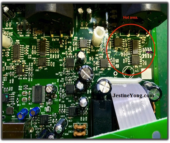
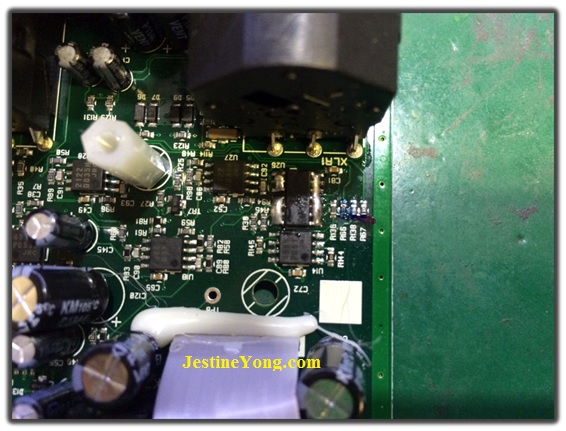
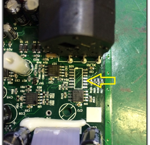
There are 3 ways I use to find shorted IC’s when doing these type of repairs. First I use my sense of touch, and feel around the board for hot areas, while the unit is powered on. I found an area with two op-amps and a Multiplexer IC that was feeling hot.
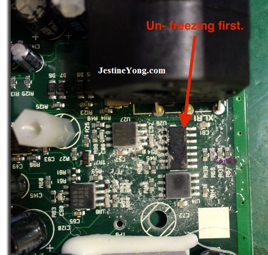
I then used some freeze spray to confirm my suspicion. The larger 14-pin IC was “un-freezing” first, long before the other two 8-pin op-amp IC’s. This means it is dissapating a lot more watts due to a short, and is drawing more current.
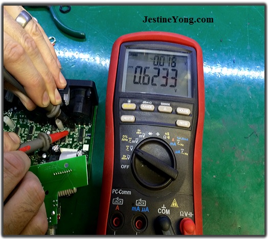
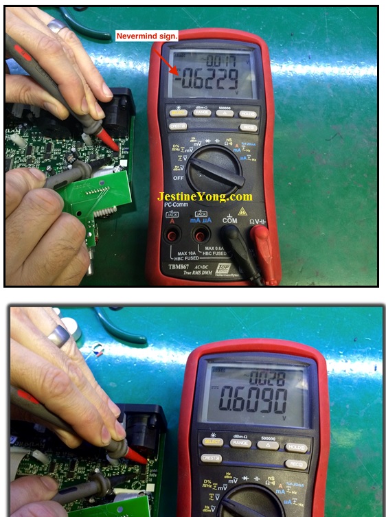
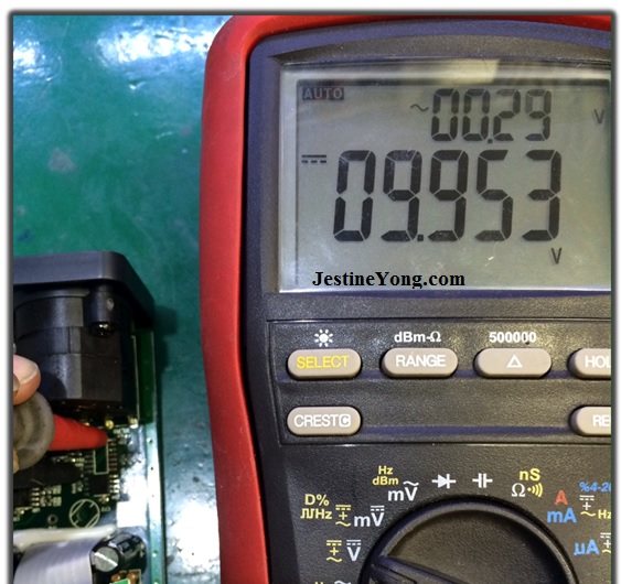
Another method you can use is by using a DMM set to ohms range, with the unit powered off. Measure across each IC’s supply pins. The one with lowest ohms reading is faulty. Usually a good IC should read a couple of Kilo ohms.
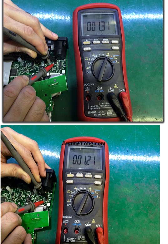
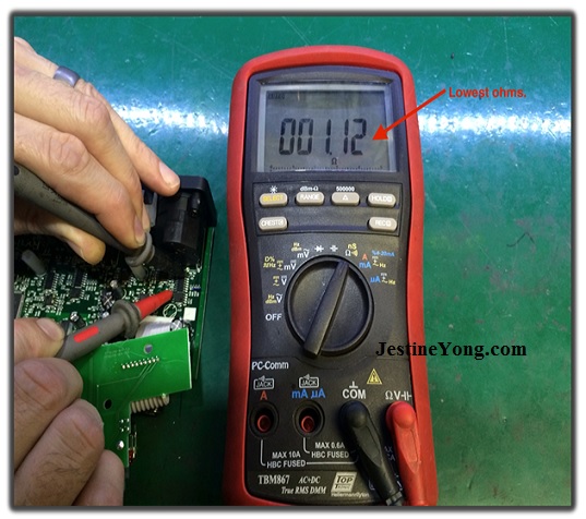
From the above pictures you can see the 14-pin IC (74HC4066) has the lowest reading of the three. Definitely shorted. Another method I use is to measure voltage across supply pins of each IC. There can still be a small voltage present even if one is shorted. You may have to put your multimeter in mV range if the voltage is too low. Here you can see the 14-pin chip again measures lowest of the lot.
This is the method I use most, as it is the quickest test. I then went about replacing this IC. First to make things easier I apply some flux to all the pins, and solder link all of them. The solder blob helps the hot air reach all pins faster.
I then remove with my hot air station and tweezers. You could use a normal heat gun.
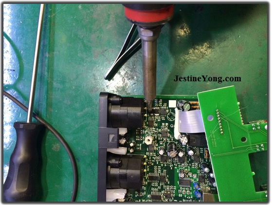
I then clear all the pads of solder using flux and solder braid, and then clean with some Isopropyl Alcohol and a brush.
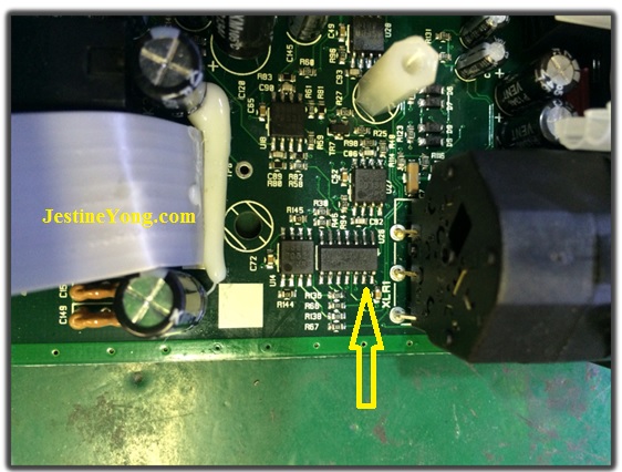
Without the faulty chip, I now measure full supply rails.
So this again confirms that this was in fact the faulty IC. Using some more flux and solder I then solder new chip in place.
After the replacement all voltages checked out fine. I hope this helps someone, as it’s just some of the techniques I use in my workshop.
Enjoy!

This article was prepared for you by Riaan Diedericks. He runs his own electronics repair shop in Pretoria, South Africa. He specializes in Pro Audio repairs.
Please give a support by clicking on the social buttons below. Your feedback on the post is welcome. Please leave it in the comments.
P.S- If you enjoyed reading this, click here to subscribe to my blog (free subscription). That way, you’ll never miss a post. You can also forward this website link to your friends and colleagues-thanks!
You can also check his previous repair article below:
https://www.jestineyong.com/subwoofer-repair/
https://www.jestineyong.com/audio-mixer-repair/
https://www.jestineyong.com/bw-subwoofer-amp-repaired/
 (263)Dislikes
 (1)
(1)
56 Comments
Leave a Reply
Cancel reply


yatta.yatta
April 14, 2015 at 8:30 am
Excellent!! Thanks for taking your time to post this for the benefit of others. Great troubleshooting and repair - many times a rarity in this day & age. 🙂
Gerald
April 14, 2015 at 8:30 am
Excellent article and repair tips Riaan. Thanks for sharing.
By the way, very nice place where you live.
Cheers,
Gerald
gerald
April 17, 2015 at 4:47 pm
ya its right sir,,
Randy
April 14, 2015 at 9:05 am
an excellent and very informative article, real electronics done here! While I appreciate the "easy" jobs that are done because there is an obvious burned component, having a job where the detective work of using electronics is much more interesting and useful, thanks!
Andre Gopee
April 14, 2015 at 9:37 am
An Excellent job done. These tip I will try in the future for repairs. One question... When you remove the Bad IC and measured the 9 volts... Was the supply on? Thanks again for sharing.
Riaan
April 14, 2015 at 1:47 pm
Hi. Yes supply needs to be on for measuring the voltage there.
Parasuraman
April 14, 2015 at 9:50 am
Nice work, very logical approach, novel way of trouble shooting. Many thanks for sharing.
Kushan
April 14, 2015 at 10:42 am
Hi Riaan;
it's very informative and enriched with much good points !! thanks for sharing !
Kushan
Sri lanka
Alan
April 14, 2015 at 11:58 am
Hi Riaan, Thank you for wonderful tips. Btw i noticed (refer to your 2nd photo)there are two electrolytic cap domed on top. Correct me if im wrong.
Cheers,
Alan
Riaan
April 14, 2015 at 1:48 pm
Well spotted! 🙂 Yes I had to replace them too. There were actually 4 of them I had to replace!!
Mark
April 14, 2015 at 12:19 pm
Hey Riaan,
Thanks very much for an excellent article. I have been doing electronics as a hobby for about 2 years now and have learnt a lot. One area that I still struggle with is IC's. Your techniques mentioned above were very helpful, but I am looking for an E-book that shows testing methods step by step. Would you know of any such book?
Once again, well written article and great diagnosis.
Robert Calk
April 20, 2015 at 5:50 am
Hi Mark,
You can go to this site an get some ideas.
http://www.repairfaq.org/sam/smpsfaq.htm#smpsadvt
Robert Calk
April 20, 2015 at 6:10 am
Mark, I found a good one that you can download and print for free.
http://repository.cmu.edu/cgi/viewcontent.cgi?article=3432&context=compsci
Ehsan Murad
April 14, 2015 at 12:33 pm
Very good . Thanks for useful techniques.
Muhammad Akhlaq
April 14, 2015 at 12:37 pm
An excellent repair tip. I normally remove only the VCC pin and check the supply rail. If it up-comes to the required value then it is confirmed that the IC under test is bad.
isaac
August 20, 2017 at 11:35 pm
after removing a vcc pin do you use digital meter or analog meter
Memo
April 14, 2015 at 2:01 pm
Excellent article. Thank for sharing.
Peter
April 14, 2015 at 2:29 pm
Nice fault finding tips,
Hicham
April 14, 2015 at 3:22 pm
awesome method, really informative article, Riaan you are expert.
Thanks to our professor Jestine.
owais akhter
April 14, 2015 at 3:24 pm
Nice informative article specially your methods of finding short.
Sodzai Razemba
April 14, 2015 at 4:16 pm
Excellent, very informative article. Every stage was explained well from start to finish and the pictures were ideal. Thank you. I look forward to reading more of your articles in the future.
Ernst
April 14, 2015 at 5:05 pm
Hi Riaan,
I like that DMM you use. I got one myself
dicksyd
April 14, 2015 at 5:59 pm
hi Riaan Diedericks good article and thanx a lot
dicksy
Bernie Scott
April 14, 2015 at 7:49 pm
Great article....I have used those techniques from time to time and they do work out great.....the one we used the most in the shop was to mV test......and like you have stated, the lowest reading is usually the culprit.....
Great job...Keep up the good work.....
Yogesh Panchal
April 14, 2015 at 9:15 pm
An other excellent repair tip from you Riaan , i just want to confirm while using freeze spray power to the circuit should be "On or OFF" ????is this spray is conductive ??
Paris Azis
April 14, 2015 at 11:32 pm
Hi Riaan
Nice presentation indeed! Given that a dead short in a power supply’s rails is a nightmare of any technician, the methods you proposed for troubleshooting it are very helpful.
Well, the “finger-as-thermometer” test I guess it’s the oldest and a fully accepted method.
Along with it, some technicians apply the “smoke it” technique, that is, “feed the circuit with an external power supply, increasing its current limit to an as high as possible level”, until you see the smoke above the dead component, meaning usually that the short does not exist any longer.
Anyway I don’t agree with this technique because the possibility of melting copper tracks of the P.C.B is always there. And if it is a multilayer construction…no comment at all…
The freezing spray, a nice trick as well, much more modern, showing the defective component very quickly, also fully understandable in its function.
Apart from these two methods, the Ohmic test I feel it is not reliable at all.
How can a technician spot a short circuit within a multitude of parallel connected I.Cs and possibly of other active components which are all fed from the same power supply?
No matter in which point you take the Ohmic measurement, the value that the multimeter will read will always be the lowest one (the dead short in other words) either if you measure on the terminals of the power supply or anywhere within the shorted loop. The short will always pull down the Ohms value to the minimum.
I used to troubleshoot cases like this one by using a very simple test jig. A D.C amplifier made of the good old uA741 op amp, having a gain between 7.500 to 10.000. So, when a short was under detection, this jig was capable of converting the microvolts voltage drop across one of the feeding lines (i.e. from the plus terminal of the power supply to each plus terminal of any suspect IC or component) into volts. I had then its output directly connected to a standard multimeter, say on its 2V or 20V range, and continuing to take relative measurements. The shorted component in the loop was simply giving out excessive output voltage in comparison to the rest of the measurements.
No desoldering and the resoldering, no stress on where to look for the culprit, nothing of the kind. A crystal clear method, fully effective in terms of time spent.
One simply feeds the circuit externally, with its nominal voltage and (reasonably limited) current and then detects the current consumption along the shorted loop.
Best Regards
Mark
April 15, 2015 at 7:33 am
Hey Paris,
I like the sound of your test jig. Do you have any photos or schematics? I am trying to get a better understanding of test procedures of ICs and would appreciate any help.
Paris Azis
April 16, 2015 at 6:38 pm
Hello Mark
Unfortunately I have nothing readily available for the time being, as I am long ago professionally inactive. I only repair electronics for my close friends now!
Nevertheless, I promise you to find the information you seek and even (most likely) write a relevant article in Jestine’s site to give the necessary explanation not only to you, but to anyone interested in electronics’ repairs.
Best Regards
Mohammed Kasim C M
April 16, 2015 at 10:03 pm
I am waiting for that
Mark
April 17, 2015 at 7:16 am
Hey Paris,
That would be gratefully appreciated. I look forward to hearing from you.
Mohammed Kasim
April 15, 2015 at 1:22 pm
Hi Paris Azis very good tips. Can you please explain it in details. I didint understand it regarding where op-amp jigs terminals are connected to the circuit?
Paris Azis
April 16, 2015 at 8:39 pm
Hello Mohammed
Jestine has issued in the past a very nice article about the many different uses of the Blue ESR meter. I suggest you to find and read this article very carefully. If you do so, you will find the answer you seek by yourself.
Nevertheless, to make the long story short, the principal idea is simply to apply Ohms Law in a clever way in order to spot the short.
So, consider the test jig as a “black box” which is fed in its input with some microvolts or a few millivolts (depending on the short circuit current) it then amplifies this voltage to a level easily measurable by a standard multimeter. This input voltage, the result of the short circuit, is detected in successive points of one of the two supply rails. Let’s take for example the negative supply as reference in this explanation.
Keep in mind that the measurements to be taken are relative. This means A) that you are not trying to measure something specific, but to note the highest reading among many other successive ones, which will tell you in turn that right in this spot is the dead short component and B) you don’t care about the possible minus sign on your multimeter, as this depends upon the connections you did before taking measurements and the usually symmetrical power supply of the op. amp. within the jig itself. So, polarity doesn’t matter. Only the magnitude of the detected voltage is what counts.
It is easily understandable that we need to feed the defective circuitry with an external P.S.U set to its nominal working voltage and supplying reasonably limited current. We cannot do otherwise even if we have decided to burn a thousand fuses in order to take some measurements.
Next, we connect one input of the jig to the minus point of the power supply. This is our reference point from now on. Then, with the second probe input of the jig we take successive measurements on the minus rail, at the points where the various ICs or other components are connected to it within the loop and we note the results. As we move from one point to the next one, if we see that the voltage indication increases, this means that we are moving in the right direction. At some point we will measure a maximum (in comparison to all the rest measurements). This indicates the dead component. If we see a drop in voltage as we move, this means wrong direction and component beyond suspicion. So we skip it and go to the next component. It is (obviously) important to measure all the components connected to the reference rail.
Once again, the highest reading reveals the culprit.
The logic (and therefore the hidden Ohms Law behind it) is that; having supplying a constant (short circuit) current to the circuit, as the minus copper track composes a resistor, by following it in the proper direction the resistor increases in value. The current being constant, the voltage increases step by step until we find a maximum where the defect is. Beyond this point, the copper track is not fed with the same amount of current, but with much less, as it is the return path of healthy components. So, the voltage drops. That’s the whole trick!
I hope that my explanation has illuminated the picture in your mind…
Best Regards
Mark
April 17, 2015 at 10:57 am
Hey Paris,
I'm starting to get a picture of what you are referring to, but an article with clear pictures would be awesome. It's great to be part of this blog and as a hobbyist - I can get years of experience all at one location.
Paris Azis
April 18, 2015 at 12:36 am
Hi Mark,
I am glad that my comment has thrown some light in this difficult topic. Just give me some time to get myself properly prepared for the article. Next, be happy to know that I had also started as a hobbyist and ended as a professional.
Perhaps it is interesting for you to know what "amateur" means in my language (:I am Greek by the way). So, "amateur" means "lover of the art" one is involved to. This is (or it should be) the quintessence of a hobbyist's qualities! And after my long involvement with electronics' repairs I have learned to respect serious hobbyists at least in as much as I do for the honest professionals! My motto is "if you don't love it, you 'll never conquer it"...
Best Regards
Jestine Yong
April 18, 2015 at 8:43 am
Hi Paris,
I liked that motto "if you don't love it, you 'll never conquer it". If you do not have a passion for a certain things you will not see good result eventhough you have put much work on it. If you have the passion you will surely excel in the things you do. And I appreciate your replied to the blog readers too.
Thanks.
Jestine
Paris Azis
April 22, 2015 at 3:27 am
Hello Jestine
First of all excuse my delay to answer you. Next, thank you too for giving me the opportunity to communicate with people interested in electronics’ repairs, especially the young incomers to this field who always need a helping hand.
This motto you liked commented is for me the most precious extract of endless time I spent in troubleshooting, some times (when I was very young…) escorted with enormous disappointment (as it usually happens with any young person, I wanted to resolve the problem “by the first sight” to it and “here and now” as well)…It took me years of reading, learning and insisting on it in order to reject this wrong attitude…
Well, I don’t know if I finally conquered it (I am still learning things from other people exchanging ideas with them), but I know one single thing for sure. That I loved it (and still do) very-very deeply…
Thank you once again!
Best Regards
Jestine Yong
April 22, 2015 at 8:03 am
Hi Paris,
You are welcome and thanks for the contribution.
Jestine
Mohammed Kasim C M
April 17, 2015 at 1:56 pm
Thank you so much for the helpful replay that illuminated the picture really. I appreciate the way you had replied.
Paris Azis
April 18, 2015 at 12:42 am
Hi Mohammed
Thank you for your good words. I am glad that my contribution was helpful to you. If you really love electronics, you will find the way to master this art. For sure!
Best Regards
Robert Calk
April 18, 2015 at 12:18 pm
Thanks Paris for your very helpful input. That sounds like what the Leak Seeker does.
I remember about using the Blue ESR meter. It is a great meter and everyone should have one.
Paris Azis
April 19, 2015 at 1:00 am
Hello Robert
Thank you too for your good words.
The Leak seeker most likely is designed on the same principal…
Best Regards
Mohammed Kasim
April 20, 2015 at 12:24 pm
I had a doubt. Can I use 741(or TL072 or LM324) op amp with R1=1K and R2=10K.
Paris Azis
April 20, 2015 at 2:54 pm
Hello Mohammed,
Be patient (young, I suppose) man!! Give me some time to get myself prepared. (I am an old man now)!!
Best Regards
Mohammed Kasim
April 21, 2015 at 12:31 pm
Ofcourse...Take your own time. Bytheby I am 28 year old. Wish you all the best. Those information which we will get from old people will be always highly valuable for the entire life time.Thanks for spending some times here for sharing information. Whish you all the best
zann
April 15, 2015 at 12:40 am
Hi Riaan thanks for the wonderful tips on your fault finding technics I appreciate . Regards
Ibrahim f Solre
April 15, 2015 at 3:28 am
Great job ,thanks for sharing your experience .
ruddyb
April 15, 2015 at 3:24 pm
hi riaan great job love it
more idear for me to used
cheers
Tito Kanshulu
April 15, 2015 at 4:28 pm
Excellent work,this has really add to our knowledge but i am not very sure with the step where voltage is applied and a DMM is used to test for drop in voltage. I think the best way on that is to disconnect a voltage pin of each ic one at a time and see what is causing a drop in voltage,that is also the best way to catch the culprit.
sydney Munatsi
April 15, 2015 at 6:17 pm
thanks for sharing your experience. I always learn from these tips.
Humberto
April 17, 2015 at 7:49 pm
Hi Riaan Diedericks, good article and good explanations. Congratulations.
kostas
April 20, 2015 at 5:56 am
Hi Riaan,thanks for sharing this!!!
Also thanks Paris ,my frind egrapses!!!
Thanks again.
Paris Azis
April 20, 2015 at 3:04 pm
Hi Kosta,
I just try to share my experiences, having dedicated my entire life in electronics, both as a hobby (when young) and as a profession later.
If my contribution works for the benefit of anyone interested in electronics this is a real pleasure for me.
Nice to met you here!
Best Regards
Rashwan Shaban
April 20, 2015 at 2:54 pm
Good Job man.
Elphius
April 20, 2015 at 10:36 pm
thanks for making our life very simple,on testing the ics,i will try this in future.great work for us Electrical & Electronics repaires
AKASH
June 27, 2015 at 6:51 pm
you mistakenly have written to turn DMM OFF while measuring short rest of the article is well prepared and quite interesting keep up!
korosh70
February 24, 2016 at 4:40 am
hi I need book repairs audio mixer and power amplifire repairs