
Beware when it comes to solder e-caps in PCBs

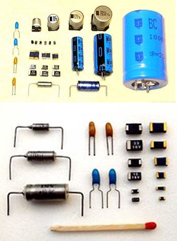
One of the electronic components that is widely used nowadays is the e-caps (electrolytic capacitors). They can be found in all the electronic appliances (more than one) of any brand or model.
The capacitor symbol may vary: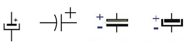
As you can see in the pictures above there are some symbols, but at the end, it’s for the same electronic component. But the most important fact, as can be seen in the photos above is that this component has polarization (+ and –) and this cannot be violated by any way when you solder it in the PCB. Why? The e-cap can explode.
What is an electrolytic capacitor? An electrolytic capacitor (“electrolytic”) is a capacitor in which one electrode is made of a metal on which a thin oxide layer forms. This layer acts as the capacitor’s dielectric. An electrolyte covers the surface of the oxide layer and also serves as the second electrode. Electrolytics have a capacitance to volume ratio much higher than to ceramic capacitors and film capacitors, but smaller than super capacitors. Electrolytics can be made with aluminum, tantalum or niobium as the metal electrode and use various liquid (water based or solvent based) or solid electrolytes (excerpt from Wikipedia).
Sometimes when you are going to solder this component, you have to be very careful regarding the polarization. For example, take a look at the photos below.
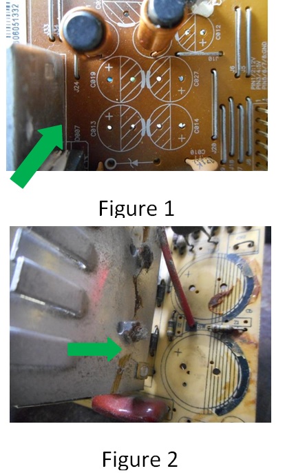
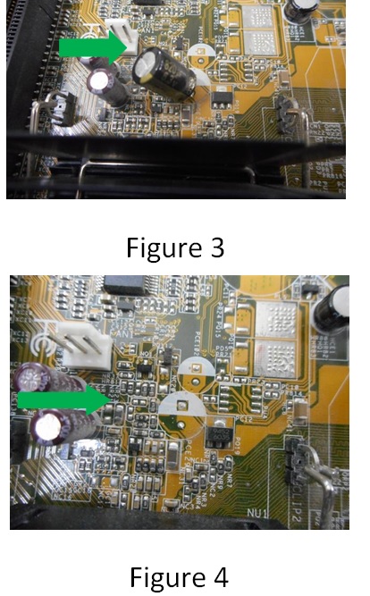
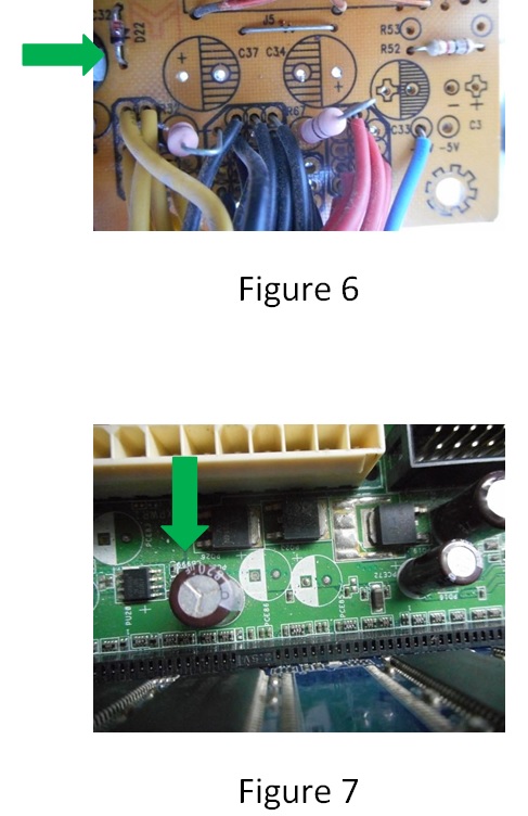
As you can appreciate in the figures 1; 2 and 6 the manufacturers have been very clear in marking the polarizations. In these three cases the + symbol is very well marked on the PCB.
In the rest of the figures the manufacturers have used another method for the signalization of the polarization, by using colors or marks. For example:
- In the figures 3; 4 and 7 the + is white-marked
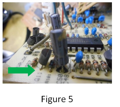
- In the figure 5 the – is black-marked.
The above marks can be used as reference.
In some occasions I’ve de-soldered some e-caps from a circuit, and when I’m going to solder the new one I’ve presented some doubts about polarization, and then here’s my advice: as all the electronic circuits use more than one e-cap I see carefully how the rest of them are connected in the circuit and now the new e-cap can be soldered in the PCB taking in consideration the accurate polarization, you can see this in the figures 3; 4; 5 and 7.
If possible before any repair work, you can take a photo of the circuit board, wire connection, connectors and etc so that you can always refer to it back when you want to fix the things that you had removed from the equipment.
Well, I hope this material can be useful for this blog readers. Thanks.

This article was prepared for you by Humberto Rodriguez, one of our ‘Master Authors’ from Cuba.
Please give a support by clicking on the social buttons below. Your feedback on the post is welcome. Please leave it in the comments.
P.S- If you enjoyed reading this, click here to subscribe to my blog (free subscription). That way, you’ll never miss a post. You can also forward this website link to your friends and colleagues-thanks!
Note: You may check his previous repair article in the below link:
https://www.jestineyong.com/daytron-electric-rice-cooker-repaired/
 (146)Dislikes
 (2)
(2)
33 Comments
Leave a Reply
Cancel reply


Gary Gemmell
November 20, 2015 at 9:02 am
Informative as ever you are my favourite engineer on here.....well after Paris Aziz he is my electronics repair hero lol
humberto
November 24, 2015 at 12:32 am
Thanks Gary, you are a sincere person. keep up
Robert Calk
November 25, 2015 at 9:40 am
Yes, Paris has a great deal of knowledge and experience. I'm glad we have great guys like him helping us out!
Merlin Marquardt
November 20, 2015 at 9:57 am
Very informative. Thank you.
humberto
November 24, 2015 at 12:33 am
Thanks Merlin.
Gregor
November 20, 2015 at 9:58 am
Thanks for your post ... I indeed installed an electrolytic backwards in a laptop ONCE (never again) ... upon applying power ... *POP* ... then smoke ... then a very bad smell like Tuna Fish. Fortunatley, I was able to replace the part (again - correctly oriented, this time) and it worked perfectly!
Be patient and double check your work before re-applying power ... kinda like the "measure twice -- cut once" rule.
George Greenfield
November 20, 2015 at 7:13 pm
Gregor,
Agreed. If you work on enough equipment and for a long enough period of time you will eventually put one in backwards. I have seen where the silk screening on the circuit card was backward also. Makes for an interesting display of sounds and odors.
We used to put them in switched receptacles for our apprentices so when they would cut on te switch it would scare them.
George
Robert Calk
November 21, 2015 at 11:09 pm
You won't put one in backwards if you are careful. Accidents are a result of carelessness.
humberto
November 24, 2015 at 12:34 am
You are completely right Gregor.
whiskey
November 20, 2015 at 10:03 am
I always look at the board after removing the cap. another thing to do is place a black mark on the board for the (-) side with a felt marker pen.
Robert Calk
November 21, 2015 at 5:59 am
I do the same thing. Safety first!
humberto
November 24, 2015 at 12:37 am
Of course if you both do this, you'll never mistake its connection.
Robert Calk
November 25, 2015 at 9:38 am
I've put one in wrong on a breadboard before, but not soldered on a PCB wrong. I always double-check the placement of anything before I solder it. But I'm in no hurry. If I did it for a living and was in a hurry, I'm sure I would solder one in backwards at least once.
Yogesh Panchal
November 20, 2015 at 1:56 pm
Humberto! Thanks for sharing this is informative material for newcomers.
humberto
November 24, 2015 at 12:39 am
Thanks Yogesh.
Robert Calk
November 20, 2015 at 6:24 pm
Thanks, Humberto. I'm glad that I have never put an e-cap in backwards.
humberto
November 24, 2015 at 1:10 am
Yes Robert connecting an e-cap in backwards is a missfortune.
Albert van Bemmelen
November 20, 2015 at 7:35 pm
Hi Humberto. You didn't mention the bipolar e-caps. Those can be placed in either way without problem. And can be made easily by using 2 identical e-caps placed in anti-serie too. Of course giving half the capacity of a single one.
Paris Azis
November 21, 2015 at 6:38 pm
Hello Albert
Yes, including the bipolar e-caps this presentation is almost perfectly completed and I say “almost” because simply it is easy to forget things! For example there is also the solid tantalum e-caps’ family into the game which have their own special characteristics…But anyway this is a nice presentation of Humberto, especially for newcomers in the “sport” of repairs.
Furthermore, in relation to your notice about the equivalence of two polarized e-caps with a bipolar one, please keep in mind that this connection you described (I agree of course and I have seen it in many relevant tutorial texts) is nevertheless not safe, especially when it comes to high currents through those e-caps.
Therefore if one is in need to build such equivalence, he/she should also use two protection diodes, one for each e-cap, with their polarities reversed in reference to the polarities of the e-caps.
In other words each diode should be connected in parallel to each e-cap with its cathode (the ring on its body) to the plus terminal of the e-cap and its anode to the minus terminal of the e-cap.
In this way the maximum reverse polarity of the applied voltage in the terminals of each e-cap will never pass the forward voltage drop of the protection diode, namely approximately 0,7V for an ordinary silicon diode and the caps will be very well protected. The total capacitance will always be, as you said, the half of the nominal capacitance of each e-cap. Of course the two caps used in this connection should be same to each other.
Best Regards
humberto
November 24, 2015 at 12:41 am
Thanks Albert and Paris.
Albert van Bemmelen
November 24, 2015 at 7:19 am
Thanks Paris for your input. In the way you mentioned also many 3 pin regulators are protected to keep the voltage difference between the input and the regulated output within their maximum specs. And that's also the way how leds are protected when placed in higher AC voltage circuits.
Tantalum 'e-caps' are known to be most aggressive little chemical containers when they deteriorate. For instance in the well known great Tektronix Oscilloscopes when they eat copper layout from pcb's! But speaking about those bipolar e-caps I do wonder if they originally also are internally protected by diodes? (I think not?)
Paris Azis
November 25, 2015 at 12:10 am
Hi Albert
I agree with all you mention.
Bipolar caps do not need any similar diode protection, simply because they are not polarized.
Greetings
Parasuraman S
November 20, 2015 at 8:26 pm
Valuable info! I have noticed that certain manufacturers, who would not like to be copied, and want to ensure that the sets reach them for service, obliterate the IC numbers and mark the polarity of electrolytic capacitors purposefully wrong! So, I have the habit of marking the + side on the PCB, before removing it! Another point to be taken care of is the voltage. We can always use equal or slightly higher voltage rating, but never less! But in circuits, when the capacitor charge or discharge is used for timing or other function, voltage would really matter! Thanks and best regards! All the best.
Paris Azis
November 21, 2015 at 5:59 pm
Hello Parasuraman
What you describe is exactly what I hate the most whenever I see it. Unfortunately I see it many times in our days. On the other hand (this time fortunately) these things are happening in very cheap and worthless products. Perhaps they could be characterized as garbage right from their birthday!
Best Regards
humberto
November 24, 2015 at 12:57 am
Yes Parasuraman, I think the best way of avoiding mistakes is marking at least one polarity on the PCB.
mahin fofo
November 20, 2015 at 10:04 pm
Each and everyone is better here
god bless you...
humberto
November 24, 2015 at 1:10 am
Thanks mahin
peter wang
November 20, 2015 at 11:50 pm
Happened to me. I am so used to pcb printed white 0r black shade for e-cap negative leg placement that I recapped a mobo without much thought. Well, the board did not work when I apply power and several of the cap bulged right away. Only when I looked at the underside of the board did I see that the square shaped solder pad which is the positive leg indication falls on the shaded portion of the ecap placement silk screen. Luckly nothing worse happened and resoldering the caps the right way made the repair worked!!
thanh
November 21, 2015 at 2:35 am
a quick tip to find polarity of an electrolytic cap on schematic and circuit board: if 1 side of the cap (the symbol) is abnormal (marked by different thing like curved, thicker, ...) it's always negative, unless positive mark "+" is clearly drawn on board
Gerald Millward
November 21, 2015 at 5:31 pm
Thanks Humberto - just the sort of practical information we all need that the books and lessons don't tell you (although Jestines books are, of course, full of such practical information).
Paris Azis
November 21, 2015 at 5:53 pm
Hello Humberto
Nice presentation!
Greetings
Hermann
December 6, 2015 at 9:06 pm
What makes me go "DUH!" is the fact that on SMD tantalum caps, it's the other way round. The bar indicates the plus pole. I've not seen many tantalums in my repairs, however that makes this an even more dangerous trap, with my mind being used to e-caps.
Gunnar Forsgren
April 7, 2021 at 7:37 pm
Japanese PCBs sometimes show the negative side of the electrolyte capacitor in THICKER size on the symbol on the PCB.
While western countries do the opposite.
Saw this on an ONKYO micro size stereo.
SO TAKE CARE TO DOUBLE CHECK and takes photos
of the PCB before you remove caps.