
Denon AVR 1604 AV Surround Receiver No Power On Repair

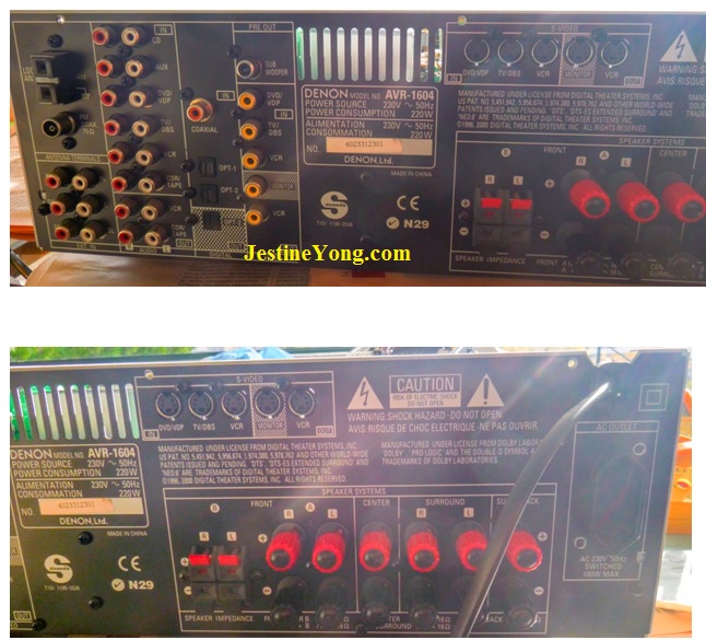
This receiver / amplifier belongs to Sofia, a woman who is close friend of my wife. Around three months ago, Sofia asked me to see what was going on with this receiver because trying to power it on, it had no reaction at all. Below you can see its back view.
When I received the unit I opened it and performed all the basic tests. Its fuse was intact, the small linear transformer for the STBY function was OK and in general everything was in good condition but nevertheless it remained permanently in STBY no matter the number of attempts to start it.
This is a very complicated design with plenty of various and different circuits in it, both analog and digital, and without the schematic diagram there was no way to go on with it. On the other hand troubleshooting it is very difficult because it uses a modular structure with many PCBs plugged vertically on the main board.
The main board is also split in two halves which communicate by means of an interconnecting board, rendering finally the servicing process almost impossible. The first half, at the left side in reference to the heat sink, includes the power supply section and everything related to audio circuitry. The second half, at the right side of the heat sink, includes all the system control circuitry.
Structures like this one always need the use of extender cards or, alternatively, of ribbon type multiple cable extensions in order to make troubleshooting feasible or at least to facilitate it. Without these specialized tools, troubleshooting this device looks like “looking for a needle lost in a haystack”.
I dismantled the unit completely removing all the PCBs from it in order to check thoroughly the power supply section. All my findings just convinced me that this circuit was OK, but still there was no power on command on the base of the transistor controlling the activation of the main power relay. So I decided to reassemble the unit until a schematic would be available.
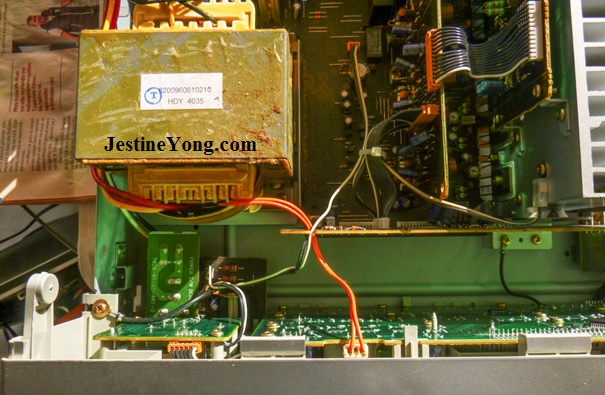
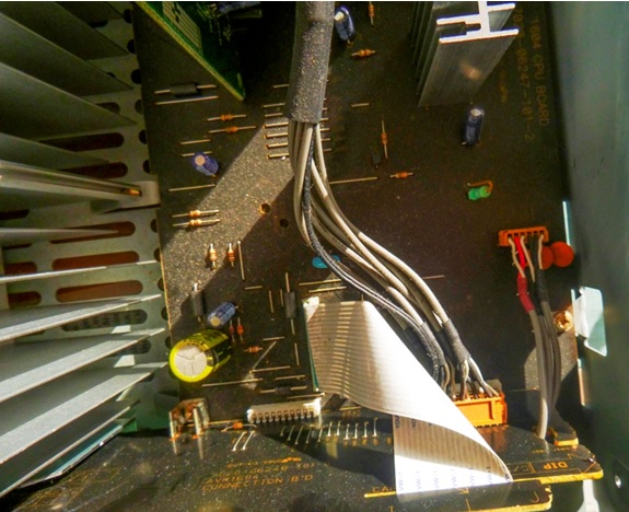
Below you can see a part of the power supply section of it. The main board shown at the bottom is the audio amplifier main circuit. Just before the heat sink is the power amplifier section, vertically connected to the main board and before this PCB is another peripheral audio circuit. The card you see vertically mounted on the edge of the main board (at the lower end of the power transformer or in parallel to the front cover PCB) is the “communications” card of the CPU with its peripherals. This brings the power on command from the processor located at the right side of the assembly.
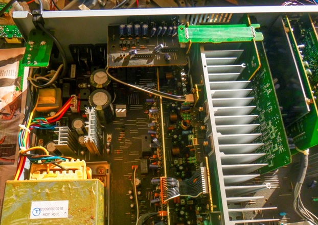
And this below is a full view of this side.
This below is the right side of it.
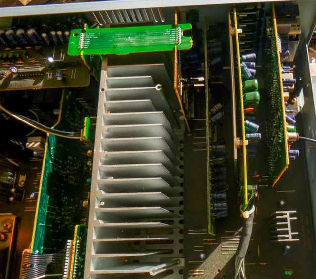
The processor is located on the back side of the (second) main board PCB shown at the bottom, in the left side area of the bunch of the grey cables shown, exactly below the two small holes shown (hardly) in line with the last two horizontally placed resistors in this area…
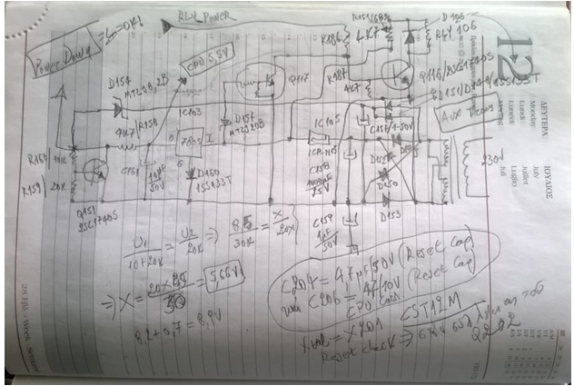
After searching in the web I found both the operating and the servicing manual. First of all I confirmed that the provisional sketch I had drawn before was correct and the STBY section was functioning properly. Below you can see a photo of my (brute) sketch, drawn in an older calendar I use for keeping such notes:
Afterwards I checked the existence of protection signals informing the processor to inhibit the power on command output. Fortunately I could take relevant measurements at the terminals of the intercommunication card. This was very-very helpful. No protection was active anyway…
Next to this I inspected the structure of the CPU circuitry, especially its reset connections. Fortunately again the small electrolytic capacitor performing the “power on reset” function was located on the top side of the main board. It is the little one you see below, right above the big golden colored one which is 8200µF/6,3V cap which maintains the user set data, the preset radio stations etc which are stored in the memory of the system.
When checking the relevant function I confirmed that this cap was also OK…I was facing that familiar condition again, where everything was OK but the device was not functioning at all…
Inspecting carefully the servicing manual, I saw an important instruction which I thought that was really tailored to fit my case. You can see it below.
CAUTION IN SERVICING
- Initializing AV SURROUND RECEIVER
AV SURROUND RECEIVER initialization should be
performed when the mcom, peripheral parts of mcom,
and DSP P.W.B. are replaced.
- Switch off the unit and remove the AC cord from
The wall outlet.
- Hold the following SPEAKER A button and SPEAKER
B button, and plug the AC cord into the outlet.
- Check that the entire display is flashing with
an interval of about 1 second, and release your
fingers from the 2 buttons and the microprocessor
will be initialized
Note:
・ If step 3 does not work, start over from step 1.
・ All user settings will be lost and this factory setting
will be recovered when this initialization mode.
So make sure to memorize your setting for
restoring after the initialization
Although I didn’t replace anything relevant up to that moment, I thought to apply this re-initialization process hopping that the mcom (the processor) will function properly thereafter.
I tried this many times, following the instruction about the case of incompleteness in step 3 above, but there was no positive result. The completeness of this step was not feasible. No display at all and when releasing my fingers from the two speaker buttons there was only flashing of the STBY led. In every new attempt, the processor was for some reason stuck somewhere in its algorithm, always at the same point.
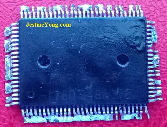
I searched to find this chip here in the local market but I didn’t find it anywhere…I kept on searching in the web and I spotted a seller of original Denon spare parts in the U.K. Now I had my hands tied because I couldn’t order it, as things are very complicated here for the time being due to capital controls…So I informed Sofia about my findings and my conclusion, giving her the necessary data of this chip, after copying them from the servicing manual, and asking her if she had a means to obtain this IC. If you are interested in this info, here are the relevant data: IC 201, Part Number: 963 0121 305, CXP 740096 -178Q, for models AVR-1604/684/AVC-1580.
Fortunately one of Sofia’s sons was working in Portugal. So she sent him all the relevant info for ordering it and sending it here thereafter. This took a long time, but anyway I had the IC in my hands a week before. Then I continued the repair process.
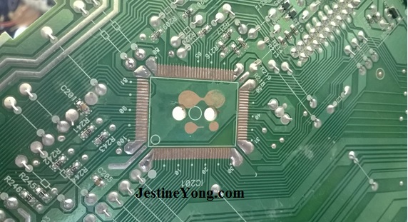
I dismantled the unit again and removed the processor. You can see below its location on the main board, after the necessary cleaning of the area.
After a long time it took me to align the 100 terminals of the new IC properly on the PCB (!), you can see below the new processor installed 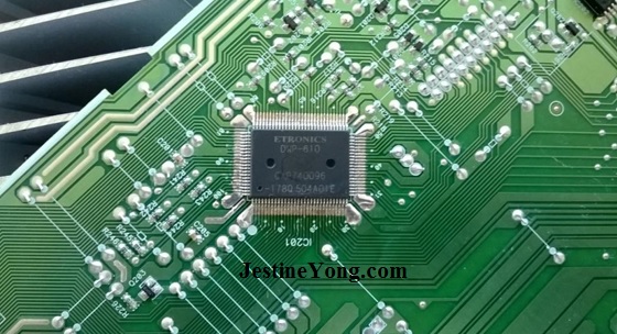
And the dead one, below
Thereafter I reassembled the unit, being anxious to see the result. You can see it in the pictures below:
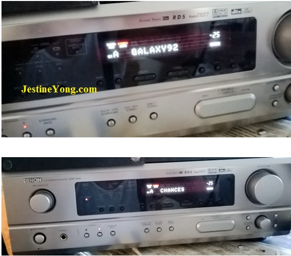
The set was functioning perfectly and I extinguished my anxiety by enjoying the high quality of the reproduced music…
After confirming that everything was in order, I informed Sofia that her amplifier was alive again and she could arrange to pick it up. She was very happy with the good news…
One more repair was successfully completed.

This article was prepared for you by Paris Azis from Athens-Greece. He is 59 years old and has more than 30 years’ experience in electronics repairs, both in consumer and industrial electronics. He started as a hobbyist at the age of 12 years and ended his professional carrier as a senior electronics technician. He has been a specialist in the entire range of consumer electronics repairs (: valve radio and BW TV receivers, transistorized color CRT TV, audio amps, reel and cassette tape recorders, telephone answering and telefax devices, electric irons, MW cooking devices e.t.c) working in his early stages at the official service departments of National-Panasonic first and JVC afterwards, at their premises in Athens.
Then he joined the telecoms industry, working for 20 years as field supporting technician in the sector of DMRs (: Digital Microwave Radio transmission stations), ending his carrier with this subject. Now he is a hobbyist again!
Please give a support by clicking on the social buttons below. Your feedback on the post is welcome. Please leave it in the comments.
P.S- If you enjoyed reading this, click here to subscribe to my blog (free subscription). That way, you’ll never miss a post. You can also forward this website link to your friends and colleagues-thanks!
Note: Please check his previous repair article in the below link:
https://www.jestineyong.com/q-tec-500w-pc-psu-repair/
 (98)Dislikes
 (1)
(1)
31 Comments
Leave a Reply
Cancel reply


Graham Robinson
May 20, 2016 at 2:47 pm
Nice work Paris, you have a lot of patience drawing the circuit out & unsoldering the chip. Did you use a heat gun or flow solder on the pins to remove it ? You did a really neat job of resoldering the chip, that must have taken you quite some time. I like microprocessors, i just wish they made them bigger 🙂
Best wishes from UK
Graham
Paris Azis
May 21, 2016 at 5:17 pm
Hey Graham
Thank you for your positive comment. As I have repeatedly commented in this blog, without patience there is no way to perform successful repairs. In my humble opinion this quality is the most necessary one in order to keep anyone to remain involved in electronics’ repairs, or to be introduced to this hobby or profession. Knowledge is of course the base but it has to do rather with safety and speed during repairs, while patience is always the motivating factor to find the reason of the defect. And its prerequisite is love about this subject…
Well, I don’t own a hot air soldering station yet. I usually apply the classic method of tinning all the pins of the IC together and heating them afterwards in a circular manner. In order to free it, when the tin is hot enough, I gently try to rise it up from a corner first, keeping on heating the pins.
For this particular chip I used another technique. I saw that in an article of the Greek version of Elector, at about ten years ago (the magazine does not exist any longer in Greek language).
I removed the chip exploiting the fact of the empty space between its body and pins. The method is to use a piece of enamel magnet wire of proper diameter that can be inserted in the aforesaid space. Then solder the exposed end to the first two or three pins of the corner of the chip. (You bend the wire by 90 degrees, after the end of the side pins of interest, and solder it there). Then heat these side pins, while gently pulling the free end of the enamel wire. The wire pulls up the pins one by one without being soldered because of its enamel coating.
The process needs to be repeated for each side of the smd IC. That’s all.
Yes, it took me about a quarter of an hour, perhaps more, in order to align the chip. It was very tricky and I confess that if I didn’t have a photo taken before the removal…it would drive me crazy. The numbering of the pins was wrong and one pin was not to be soldered for the alignment to be feasible…!!!
After the alignment I tinned the pins and used a conical tip in my Weller soldering iron having an oval cut. This removes effectively all the excess tin and frees any shorted pins…
I also like microprocessors but I confess that I hate the smd technology and the lead free solder!!
Best wishes from Athens/Greece!
Parasuraman S
May 20, 2016 at 3:38 pm
Very unique servicing, indeed! I bow in respect for your ability to remove and solder a replacement IC, which many like me, may not venture to do! Drawing a complicated circuit by hand is a another! I am lost in sheer admiration, getting proper words to express!
Paris Azis
May 21, 2016 at 5:30 pm
Hello Parasuraman
Thank you for your very kind words. Yes, the replacement of such ICs is very difficult indeed, especially if the proper solder/desolder stations are not available, but finally everything in electronics is a matter of patience, which in turn is a product of strong will to restore the normal operation of the defective device…
And if all the easy static measurements of components reveal no problem, drawing the suspected circuit in order to understand what is going on, is the only option, when no schematic is available, to get you in your destination…
Best Regards
Anthony
May 20, 2016 at 4:30 pm
Is it a bird....is it a plane...No it's Super Paris ! Able to leap "Tough Dog" repairs in a single bound ! Well done Mr Paris with your determination in solving these electronic mysteries and sharing your experiences here for others to enjoy and learn from. Well done again !
Kind Regards
Paris Azis
May 21, 2016 at 5:42 pm
Hey Anthony
Thank you for your…poetic approach of your comment. And yes, if the repair works like a mystery it attracts you and you move on ending with it successfully. On the contrary if you keep on seeing your watch and thinking how much time you spent and…still nothing…there is no chance for repairing the defective equipment. It is quite simple (although, I admit that, not always feasible for a professional). In any case, my permanent advice for repairers is: forget the time parameter when repairing and you will succeed.
Greetings
Yogesh Panchal
May 20, 2016 at 4:39 pm
Paris,
"Professional Repair approach" good Job!
Paris Azis
May 21, 2016 at 5:44 pm
Yogesh, thanks a lot for your positive comment.
Best Regards
skwong
May 20, 2016 at 4:57 pm
You have a lot of patience and done a very good job. I hate to repair amplifier system, as it is difficult to access the test points.
Paris Azis
May 21, 2016 at 5:59 pm
Hey skwong,
Repairs is a synonym of patience. At least in my opinion, based exclusively on my own experience over time, this is self evident. Furthermore I would say that I fully agree with you as regards the difficulty to access test points when repairing amplifiers, but I always take it as a challenge to overcome this obstacle by using my imagination. For example, there are countless cases where I used ribbon type cables in order to extend the connections and have a peripheral card properly available for measurements…All what is needed is patience…again…
Best Regards
Albert van Bemmelen
May 21, 2016 at 3:54 am
Hi Paris, A Great job done!
It is always a small gamble if a semiconductor with so many pins will survive the soldering. And if there are no ESD complicating facts that easily could ruin any new Chip.
My pinwise largest chip (it probably was a bit smaller than yours but had also 100 pins?) thus far that I succesfully managed to replace was an Atmega 2560 AVR processor on a Arduino ATmega 2560 Board.
And I only used a Hot air Nozzle to remove the old Chip and standard solder afterwards to place the new one. But it is not something I like to repeat easily! Glad your repair also worked out so well!
Paris Azis
May 21, 2016 at 6:06 pm
Hi Albert
Thank you too for your kind words. I agree with your thoughts about the risks when replacing such ICs.
If you are interested about my method for their removal, you can see some details in my answer to Graham, above.
Best Regards
Albert van Bemmelen
May 23, 2016 at 9:25 pm
I've read and understood the way in how you managed to remove the old chip. Sorry to hear that you do not own a Hot Air Solder/desolder Station yet. Although you not always need one they have improved in the last year or so too !
They are now equiped with a small blower inside the begin of the handle of the nozzle holder. So they do not need the old big teflon hose anymore which makes them less heavy and much easier to handle.
By-the-way: I read Elektor (used to be called Elektuur in Holland) since around 1977 now. And I am still a subscriber since 1979 I guess. Sorry that the Greek version of Elector, siezed to exist about ten years ago in your Greek language.
I have a great lot of all sorts of old (and new) electronics magazines, in almost any language (not in Greek though I'm afraid).
Paris Azis
May 24, 2016 at 3:24 pm
Hey Albert
Although the truth is that I don’t need a hot air soldering station for everyday use, can you propose to me a reliable and relatively economically affordable unit? Thank you in advance.
Best Regards
beh
May 21, 2016 at 10:33 pm
Hi Paris
this is a super article .but I have just one question about the program of this ic. is this new processor was programmed before to reach to you and/ or you programmed this ic? if you did from where you received the program ?
thanks
beh
Paris Azis
May 22, 2016 at 4:28 pm
Hello Beh
Thank you for your supporting comment. The IC I replaced was original spare part and therefore was programmed. That’s why its cost was 45₤ (:U.K pounds). I found it non programmed, manufactured from Sony, at a cost of five pieces for one euro (if I remember correctly)!! But I had no way to program it…
Best Regards
beh
May 23, 2016 at 1:14 am
Hi Paris
thanks for reply .i understood that:the original ic was programmed by manufacturer but was not functioning properly . and you had to replace it but the new ic was empty and you reprogrammed this one
and installed on cir cute . but you did not answered from where you received this program ?
thanks & regards
behzad
Paris Azis
May 23, 2016 at 7:12 pm
Hi Beh
Obviously you misunderstood me. I bought this IC pre-programmed (as an original Denon spare part).
Best Regards
Robert Calk
May 23, 2016 at 12:56 pm
Excellent work, Paris. I'm glad you were able to find a pre-programmed MC.
Paris Azis
May 23, 2016 at 7:31 pm
Thanks a lot Robert. Indeed, I was lucky with finding this new processor pre-programmed...I had already spent a lot of time in order to conclude that it was defective and it would really be a pity not finding it (and I hate this when it happens)…
This sad situation would be worse for our friend Sofia, because she paid a lot of money to buy this (very expensive at the time it was bought) equipment. Moreover, as she told me, trying to understand why this amplifier had failed, she was using it rarely…Well, who can answer that?...
Best Regards
Humberto
May 24, 2016 at 11:33 pm
Wow! Paris, what a pacience and professionality! Another device saved from the dump.
Paris Azis
May 25, 2016 at 4:16 pm
Thanks a lot Humberto.
Best wishes
silvio cabral viveiros
July 9, 2016 at 6:46 am
Hello.
I live in sao paulo , Brazil and have a denon with the same problem . accurate and here no sign ... but I also have relatives in Portugal . What should I do so that they can acquire the to send me ? which direction should I give them?
grateful.
Silvio Viveiros
Paris Azis
September 7, 2016 at 6:01 am
Hello Silvio
Sorry for the delay to answer your request, the reason being that I do not have the needed time to revisit my published articles so often. As regards your request, I am afraid I cannot give you any advice in blind, without even knowing the model you own. I would only suggest you to try to re-initialize the processor (if the symptom as you say is similar). The method is given in the text above and it is easy. If this doesn’t work for you, I thing the only further option is to send the unit either to an official Denon service in your country or to a known skillful repairs’ technician located at the place you live.
Best Regards
Fabrice
September 8, 2017 at 6:32 pm
Hello Paris, thanks for your analysis.
I have the same problem, when i turn on, it romains off aster turbine on several times randomly...
Now, i don't find where i can buy the CXP !
Can you help me please ?
I live in France
Paris Azis
March 13, 2018 at 1:42 am
Hello Fabrice
Sorry for the long delay to answer you. I had googled the chip and found it in England. Unfortunately I don't have the specific address of the company that had it available. I hope this helps your case...if you didn't already have fixed it...
Ralph
July 30, 2018 at 9:20 am
Hello, good job, I just wanted to ask you if this chip (mcu) needs any update or installation of a program, a firmware, or just changed nothing else, I ask you because I also have a similar problem with a receiver Denon S500bt model, in the technical manual says it. Thanks for the reply
Ralph
August 14, 2018 at 2:51 am
Hello, I just want to ask you, if you programmed or installed the firmware to that chip. Thanks for the answer
Paris Azis
February 21, 2019 at 5:26 am
Hello Ralph
Sorry for the delay. I rarely revisit my articles. Well, I bought this chip preprogrammed from U.K.
Thanks for your kind words.
Emanuele
June 10, 2020 at 5:28 am
I, i have a similar problem with Denon 1802.
I'm trying to understand if the PROTECT pin of CPU should be high or low level when fully functional.
My receiver stays in stand-by mode, and i have 5v on PROTECT CPU pin. I don't understand if this should be 0 v or it is a (NOT) value, so 5 V is correct. Did you remember the value of yours?
Thanks
Wattana
September 14, 2021 at 6:35 pm
Hello Paris,
I'm facing the problem like you stand by power are working well but relay did not turn on main Transformer. I've service manual with me but I'm a bit confuse on RLY_POWER signal. Which part does supply this signal to turn on main transformer relay between CPU board and stand by 15VDC thru Q117?
your kind suggest on this matter is much appreciated,