
Not Common To See Duoyi DY294 Tester Taken Apart And Repair-Part 1
As a very interested Electronics repair engineer I love using new Test Gadgets and Digital Meters and new Testers in my Electronics Hobby at home. After all they do make our lives easier and repairs less time consuming. And recently I bought the DY 294 which I received with a Chinese Manual, after reading the very positive articles on the site from Jestine himself with a link to the English Manual.
Strange enough the Chinese manual spoke about using a 2A 6V adapter whereas the English manual spoke about using a 3A 6V adapter. Because Batteries would be empty in no time!
So I thought it would be fine if I didn’t use Batteries. And I chose to connect the DY294 to an external adapter 6V 1A instead.
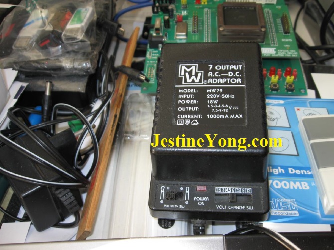
But I couldn’t have been more wrong! Although I used an original 6V 1A (18W_7 output 1.5-3-4.5-6-7.5-9-12V DC model MW79) adapter, it destroyed my quite expensive DY294 Tester within about a minute !! Because the LCD went dead after this. See next photo of my DC adapter that destroyed my DY294.
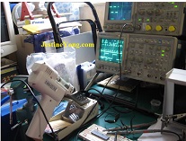
I tried if the Tester would come to life again when I used Batteries, but the Meter/Tester stayed completely dead. At least on the LCD display because I still could measure HV and Voltage Stabilizer Input Voltages (about + and – 30 V DC) on the front connectors. And I guess that the unstabilized 6V DC voltage was unloaded just a bit too high for the internal controller chip.
And because I wasn’t warned about this assumably very easily and unexpectedly occurring problem, I hoped to hear from the Manufacturer. In the expectation to receive a schematic of some sort or at
least some information needed to repair the about $45 US dollar costing device. But I got no answer from the DUOYI Manufacturer at all.
Although I could have send it back to the seller on Ebay, claiming my 1 year guarantee, I chose not to because Shipping cost with Tracking and Trace and maybe also sending it back to me would be not cheap and probably more expensive then buying a new DY 294 again.
And my Ebay seller was very grateful I kept my now defect DY 294 and I afterwards bought a new second DY294 from them. But I did ask them to please contact the Manufacturer for any information they would be able to give. Also about buying the DUOYI 3A 6V adapter because it wasn’t mentioned anywhere in the manual how to obtain one, and its price neither. And that their DY294 Manual really should warn about anything like this to happen.
But after all I am a repair engineer and that is what I intended to do with my first now defect DY294.
After gathering all information from the device, this article now gives you all information that you need to repair any blown DUOYI DY294 Tester yourself! Also being the best and now only available Service Manual to undertake any DY294 repair.
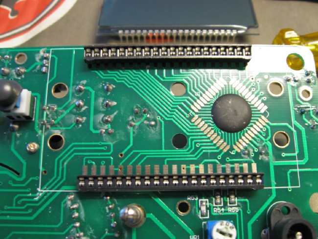
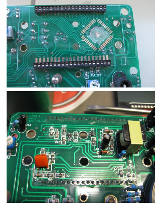
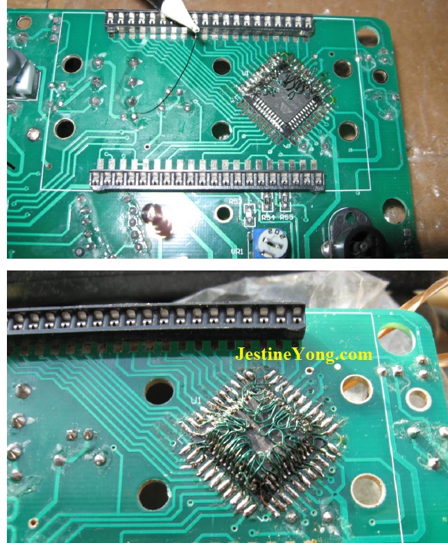
Following Photo shows the only chip and also being the LCD controller inside the DY294. This chip is mounted on the pcb right under the 40 pins LCD. This at that moment was a 44 pins unidentified SMD mounted controller. And this defect chip is most likely the only cause of the defect DY294.
And the second Photo shows the 40 pins LCD just before removing. With the controller under it.
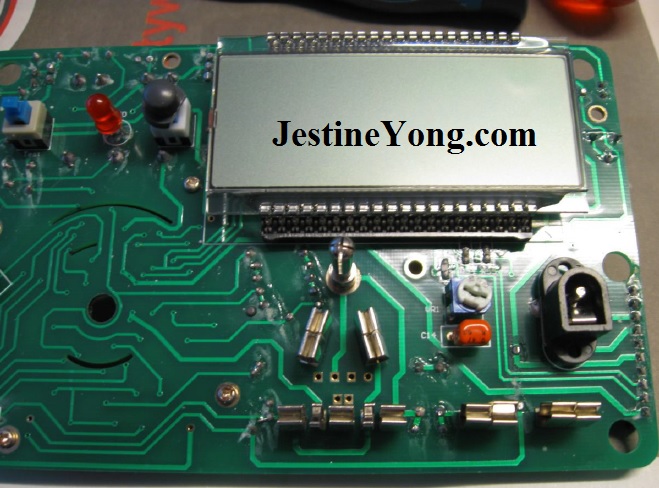
I had no clue what controller was used because it had no markings. But I knew that I could examine the display functions in the LCD by touching any of the 40 pins of the display by using a metal screwdriver. The contact potential voltage would enable the connected segment of that pin. And with this information it should probably be very easy to destillate what controller was used inside the DY294.
Following picture shows the LCD pin functions:
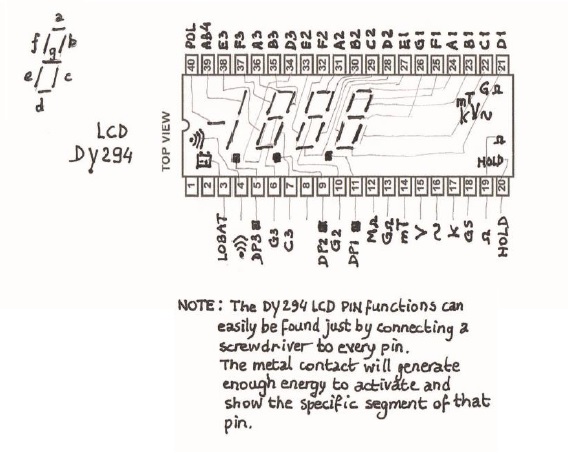
NOTE: THE LCD PIN FUNCTIONS CAN ONLY BE FOUND IN THE ABOVE DESCRIBED WAY WHEN THE LCD IS STILL ‘CHARGED’ FROM THE TESTER SOCKET NOT LONG AFTER IT IS REMOVED FROM THE BOARD SOCKET !!
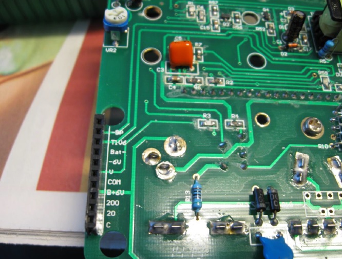
Previous Photo shows the back of the pcb with the back of the LCD connector and with a view on the (not overvoltage protected!) 6Volt DC input jack.
As can be seen on the pcb connections to the controller chip it can’t be a ICL 7116 chip because this would mean that the 3 pins: V+ (pin 43), Common (pin 40), and IN LO (pin 38) would short circuit ! Although we would need the HOLD signal on Pin 5 from the ICL7116. Therefore it can’t be a ICL 7116 chip that is originally used in the DY294 Tester!!
And although a ICL 7106 chip would fit without short circuiting because the previous V+ pin 43 is correctly a REF LO function that needs to be connected with COMMON and IN LO, it also is not the correct needed chip because it misses a HOLD pin 5 ( NC pin on 7106), and doesn’t have a BATLO pin either (PIN 33 LB). And our Tester needs that function too!
Searching on Google for a ICL 7106 pin compatible replacement with extra HOLD and LoBat pin gave no result.
But after examining my 8 euro cheap DT9205A Digital Meter circuit I noticed an AME 7106 chip that is completely pin compatible with a ICL 7106 controller but with the necessary extra HOLD and LOBAT functions. So although Google didn’t help me I found my chip that most likely is used
originally in the DY294. First I looked on Ebay and thought it couldn’t be found there. Which probably would mean I had to buy another cheap DT9205A meter and remove the needed chip from there.
But later I luckily found a $6 dollar smd AME7106 chip on Ebay plus shipping $6 dollar. A bit more expensive but without the hassle to destroy a good Digital Meter and it makes the new chip a better fit than an already used one .
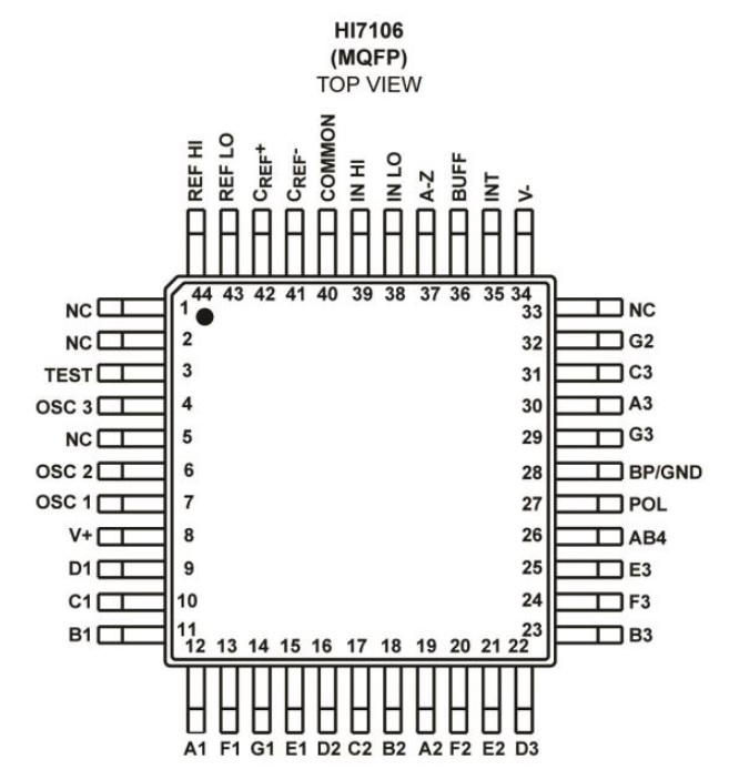
Above a ICL 7106 controller chip that almost is identical to the in the DY294 used chip. Because also pins 5 and 33 need to have an active function in the DY294. (pin 5 is HOLD, pin 33 is Lo Bat).
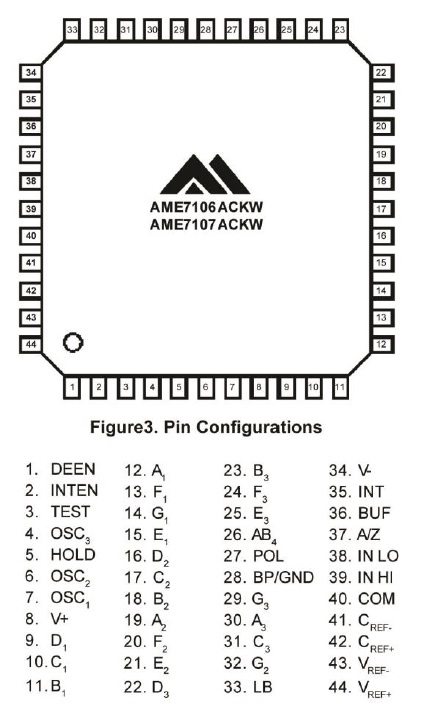
The AME7106 however is the correct chip for our DY294! See following picture from the AME7106 datasheet (Pins 1 and/or 2 are probably not used however. And Pin 3 is only a means to test if all your LCD segments are OKAY) :
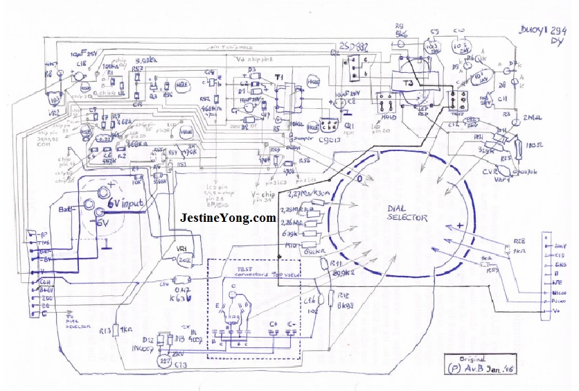
Next picture shows all components used in our DY294 tester (all R values are measured in circuit with a Digital Meter and give a good idea what the right value is):
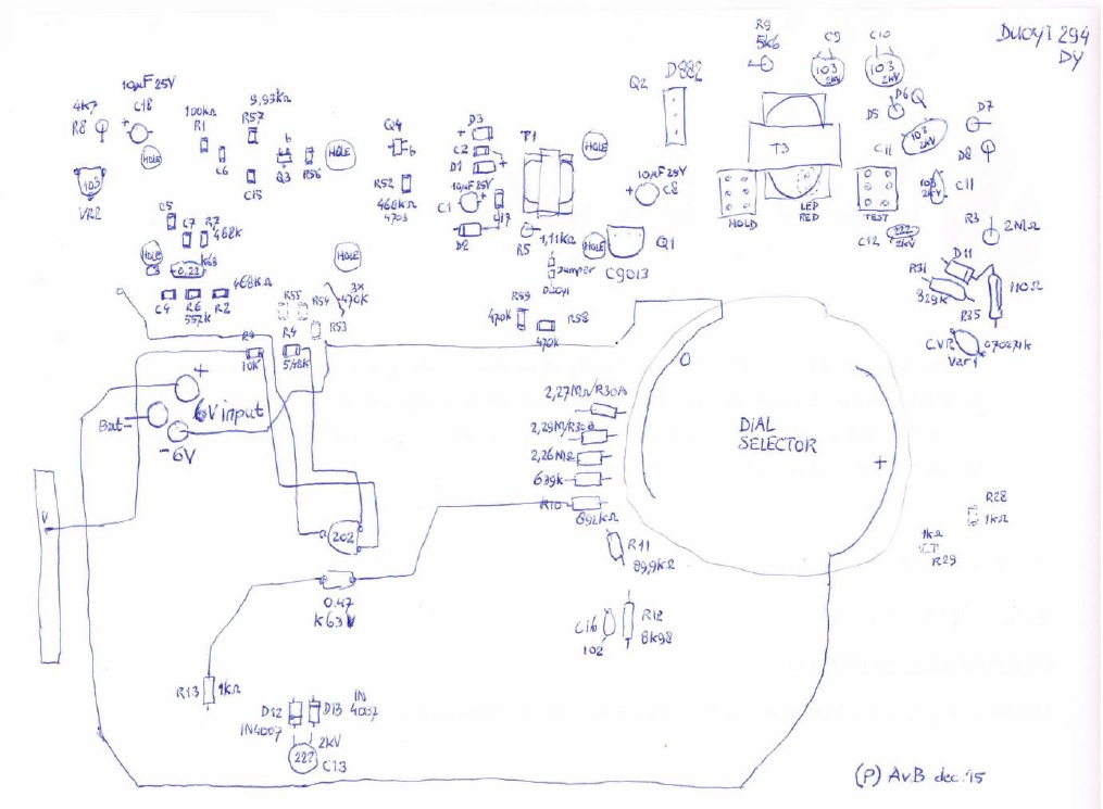
Q3 and Q4 in above circuit are NPN transistors according to their SMD code 1AM, resp 1AMe. R5 probably measured wrong about 1.11K possibly because of a bad Q1/C9013. (R5 is likely 19.05Kohm).
So according to this article about the DUOYI DY294 semiconductor tester you need to be very careful to use just any 6V DC adapter as it most likely will mean the end of your expensive Tester/Meter. And you won’t be warned in the manual but you now are informed! And with my here presented repair instructions you will be capable to repair your device.
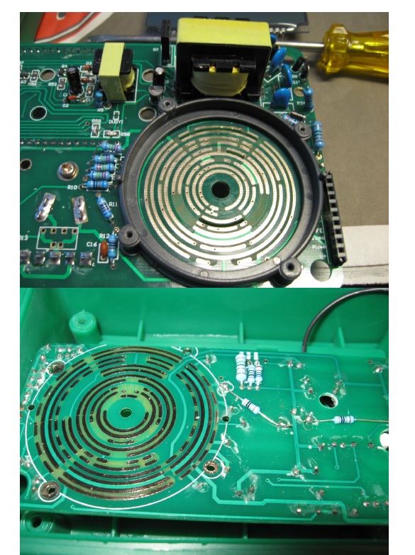
Following photo shows how I removed the bad DY294 controller chip (by carefully using a Kinzo Tool) to make sure it will not inflict with the new replacement chip, our AME7106 chip, that will be soldered on top of the old safely removed one. And I also flattened the epoxy of the pcb afterwards a bit, after having removed the bad chip there with the Kinzo, by using some drops of superglue on top of the epoxy too.
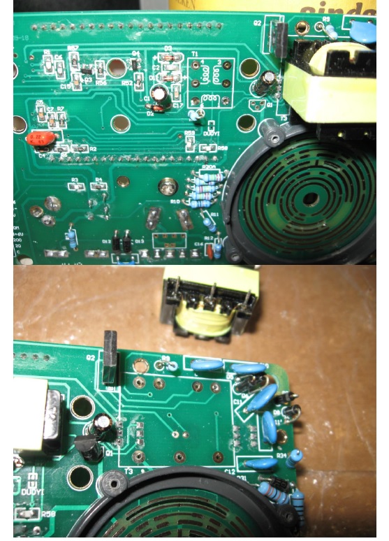
Next photo shows the back of the LCD connector with Q3 and Q4, and to the right also Q2. And Q1 under Q2 on the right from Transformer T1.
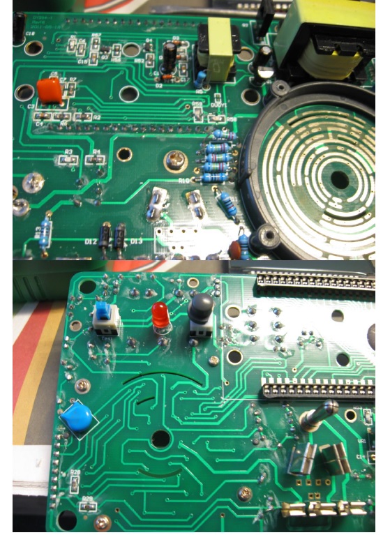
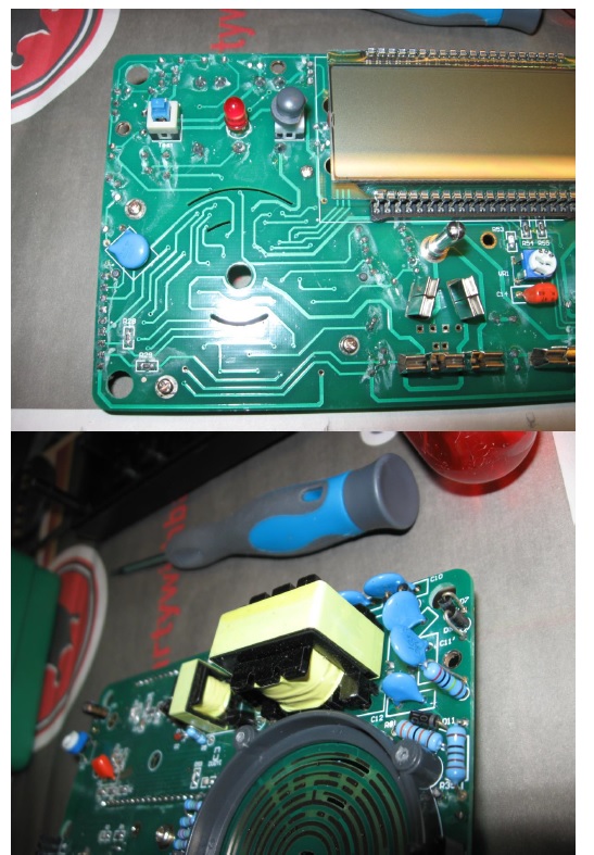
And following last photos show more views on the DY294 pcb.
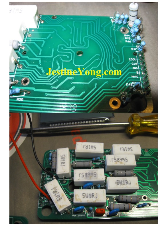
Funny thing about this DY294 Meter is that the Function Dialing knob doesn’t use any springs to press onto the contacts. Because it nicely is rotating between 2 pcb contact strips under and above the rotating knob. The copper contacts itself, on both sides of the rotating knob, are used as a kind of springs to keep the right contact. (Careful not to change the copper spring contact positions on the knob!). And that is maybe no bad idea in itself compared to the way in which standard Digital Meters like the DT9205A work. (The knob is assumably the most expensive part of any normal digital meter).
Today my second DY294 Digital Tester arrived I ordered after my first DY294 was blown by unexpected DC overvoltage. Since I probably need the new working tester just to be sure my repair DY294 device is functioning exactly like the original calibrated one. Sadly my new DY tester had problems with the E C B contacts why the 3 pin Stabilizer 78x and 79x tests completely failed. Just as the transistor tests. And so I had to open my new DY294 to correct the connector clamps that didn’t make any contact with any of the inserted semiconductors. Again something that any other buyer wouldn’t have accepted but I am not any ordinary buyer. And I fixed the contacts so they worked like was to be expected. And I closed the new DY294 after I had send a message about this new problem to the Seller were I also got the first DY294 from.
Strangely there the problems didn’t end because the new DY294 did have a large deviation while I was testing an 18Volt 0.5Watt Zener diode that only gave 17Volt on the LCD. And 1/17×100% is more than 5.88% tolerance (minus). Which most likely also is a bigger deviation as compared to measuring with any ordinary Digital Meter. But only when (as a test) I did put the Zener in the Capacitance Test Socket it gave exactly 18V on the display.
Reading the Chinese and English Manuals I couldn’t find anything that would give any exact tolerance figure about measuring the Zener Voltage. But I did find an error in both Manuals (pages 9 and 11) were the left TO-220 three terminal voltage regulator should be a 79x type instead of a 78x type!
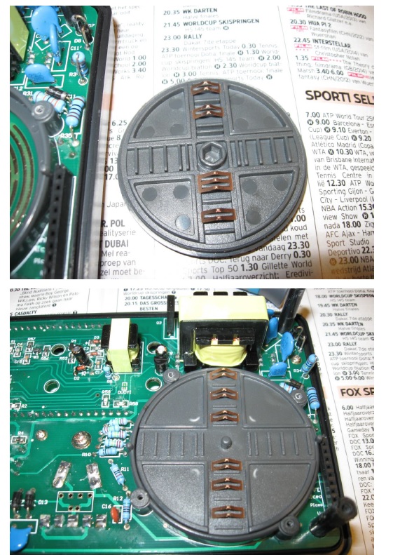
And before we end this repair manual for the DY294 we do also need following information about the Dial Knob and its contacts. Because when they get loose you have to put them back at the right place on the Knob.
First Photo shows the copper contacts that go with this side on top of the Front dialer axle.
Next Photo shows the other side with the contacts that stay visible when the dialer contact wheel is put back in place. So the second and also last photo of the Dialer contact wheel shows exactly how the Dialer wheel/knob is assembled correctly before closing the Housing/case of this DY294. And in this position you have to make sure you put the front Knob pointing to the top OFF position!!
The Calibration of this Digital Tester is limited to only 2 potentiometer adjustments. And this Digital tester is in fact controlled by an ordinary Digital Meter ic that in itself already has a few auto calibrating (offset correction) features. See for more info the Datasheet of the AME7106 controller that also has its own internal Voltage Regulator Circuit.
With all in this article given information, repairing a DY294 Digital Semiconductor Tester should be no problem anymore whatsoever. And later on I also found out that the AME7106 is even sold on Aliexpress for only about $1.50 per 44 pins smd chip.
My conclusion is that this DY294 is a very well Special designed digital Tester/Meter except for the part that the 6V DC input isn’t internally overvoltage protected. (Hence what made me write this article in the first place!). Which won’t be any problem when using Batteries only, like it is the case with any Digital Multi Meter that uses a single 9V battery. But because it is advised to use an external High current adapter, a specific warning to use only a perfectly stabilized Adapter would be the least you should want to read about in the DY294 Manual. Or for that matter you should expect to read on the Front of the DY294 at the 6V Power input. But sadly the only thing that it says is 6V DC and that is also the same text that was written on my 6V 1A DC Adapter. And some kind of overvoltage protection therefore wouldn’t have been a bad thing. And I guess that a lot more DY294 buyers encountered this unexpected problem too! And compared to any ordinary Digital Multimeter the number of components used inside the DY294 is surprisingly low. There is for instance as far I could see not one op-amp used inside. And normally every DMM uses at least one for the automatic Power Switch off circuit. And while saying this, I also notice that this also is the reason that the DY294 doesn’t have this Auto Switch Off function.
I examined the max allowed Voltage requirements between the available LCD Digital Multimeter controller chips. And our DY294 most likely controller AME 7106 is very specific as it only safely operates when V+ is max 6 V and V- is max -6 V! (That is V+ to V- is a maximum of 12 Volt DC!). And it therefore operates without problem when the supplied voltage is a 9V battery between the V- and V- power lines. This also makes clear why it is so easy to destroy the DY294 without any warning! However the V+ and V- Voltage over D2 being +3.07V and -7.12V could be at least on the negative V- voltage a bit too high. Which could destroy our Controller chip? (But keep in mind that D2 is no normal Diode but a 10V Zener diode to prevent blowing up the controller!).
The HI7106 or the ICL7106 LCD controllers however have no problem when the Voltage between V+ and V- is 15Volt max! This means +V being max 6V and the V- max -9V!! (is a total of 15V between V+ to V- supply lines). And here also a 9V battery can be used without any problem on the V+ and V- lines. The 9V DC will be divided in +4.5V on the V+ line to GND. And the V- voltage to GND will be minus -4.5V.
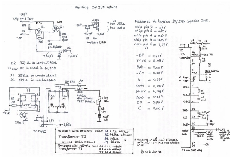
To explain what values a good working DY294 measures, following Information finally gives a good presentation which most certain will come in handy. (Of course some values depend also on the position that the Dial Selecting Knob is switched in).
And it shows that Q2 (2SD882) with Transformer T3 makes all High Test Voltages. Transformer T1 with transistor Q1 (C9013) generates obviously the Voltage on which our LC Display operates (V+ and V-). And Transformer T1 consists in fact out of 3 coils. Although there is a T3 transformer. There is no T2 transformer on this Board.
One coil is in the Base of Q1, the second coil of T1 is the primary input connected to the collector of Q1 and it switches the T1_V6 input battery/adapter voltage. The third coil is the induced voltage that generates the higher Voltage that after rectifying makes the LCD DC operating Voltage.
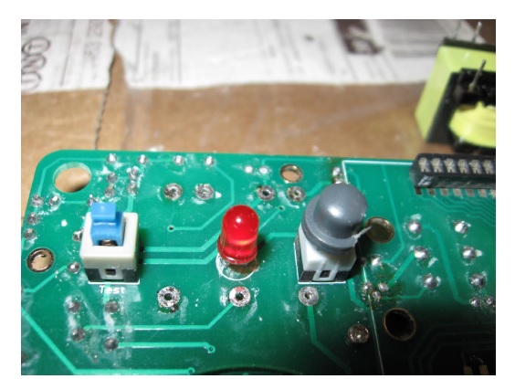
It also shows that there are only 2 adjustable variable resistors in the DY294, being: VR1 which adjusts the Vref+ level into our LCD controller chip, and VR2 that adjusts the High Voltage level coming from transformer T3. (Which becomes active including the Red Led when we press the TEST Button).
Here also follow some photos that show how both Transformers T1 and T3 are wired and placed on the DY294 Board. As you can see T1 and T3 are practically used in exactly the same way.
I removed both Transformers to be able to measure their construct values. I used my new built M12864 Graphic Version LCR Transistor Tester to determine the Coil values.
Transformer T1 consists, as can been seen on the previous photos, out of 3 coils labelled pins 6+1 (on Transistor Base), pins 2+3 (primary coil) and pins 4+5 (secondary coil).
And my M12864 tester gave coil pins 6+1 a value of 0.0 ohm at 0.05mH, coil pins 2+3 gave 0.2 ohm at 0.62mH and coil pins 4+5 gave 0.1 ohm at 0.13mH. I took the Transformers from my defect DY294 and later also compared T1 with my second working DY294. And got these T1 measurements: Coil 6-1-> 0.2 ohm 0.04mH, Coil 2-3-> 0.3 ohm 0.61mH, Coil 4-5-> 0.3 ohm 0.12mH. So likely the M12864 Tester deviates a bit in presenting at least the Ohmic results. And R5 likely is a 19.05K Ohm resistor.
And my M12864 Graphic ESR/LCR/TransistorTester gave following values measured on the Bigger Transformer T3. The Primary coil connected to R9 measured 46 ohm without any mH or uH value. Same with second Primary coil that is connected to VR2 that measured only 78.2 ohm and also no mH/uH value. And the remaining 3 pins on the T3 Secondary High Voltage consists of 2 coils . The Secondary coil between the Middle pin and the outer pin directly connected to C9 labelled 103 2KV gave a value 44.8 ohm and 256mH. And the last Secondary coil from the Middle pin to the outer pin that is directly connected with one side of C12 222 2KV gave a value of 4.5 ohm and 68.7mH. The total Secundary Coil value measured on both the Outer pins gave 49 ohm at 588mH.
To be sure about the Ohmic results I also took measurements with my Digital DT9205A Meter on the 200 ohm scale. Both Primary coils on T3 gave an 0.4 ohm value. And first measured Secondary HV coil gave a value of 45.8 ohm and the last coil gave 4.4 ohm. R5 in-circuit measured 18.20 K ohm.
Although my first DY294 only worked for about a minute or so, the DY294 is a unique and well-priced Testing Device after having read Jestine’s great article on the DY294. It already made me therefore buy another one on Ebay. So having two of them soon won’t be any problem whatsoever. Only getting the right 3A 6V matching stabilized 6V adapter was a problem until recently! I finally found the right adapter on Aliexpress for about 6 euro. (Ebay assumably had only 2A 6V Adapters. If the Chinese Seller on Aliexpress only had send me the correct EU AC plug adapter as I had ordered).
And if you abusively still do destroy your DY294, like I did, this article could be a great help to repair your device again too! But first check if 2SC9013/Q1 is still working before you remove your controller chip thinking it is destroyed. Next photos give you an idea the trouble I had to replace the removed chip by the pin compatible 44 pin AME7106 LCD controller!
First photo shows the replacement chip after unpacking.
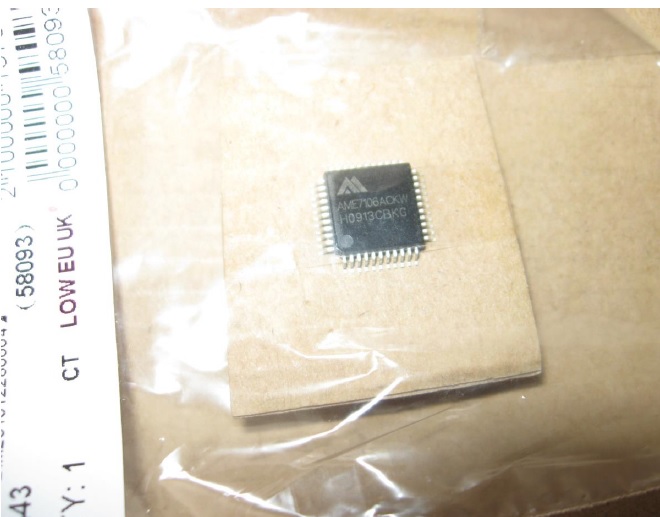
This chip should be the exact replacement type for our DY294 LCD controller. At least all LCD segments and the Bat Low, and HOLD functions should work! But we only can be sure after it is soldered onto our DY294 Board. But that ain’t easy as following photos show.
Next photo shows I had to solder 44 0.2mm thin wires from smd chip to the copper layout!! On the photo I was only half way…. And after every new wire I checked if it wasn’t shorted with the previous connections. I used a Wiring pen that already helped me to produce many projects without having to create or etch a copper layout pcb first.
This job doesn’t look easy but I did it with my 25 year old standard Ersa MS6000 solderstation. Click HERE to go to Part 2.

Albert van Bemmelen, Weert, The Netherlands.
Please give a support by clicking on the social buttons below. Your feedback on the post is welcome. Please leave it in the comments.
P.S- If you enjoyed reading this, click here to subscribe to my blog (free subscription). That way, you’ll never miss a post. You can also forward this website link to your friends and colleagues-thanks!
P.P.S- Note: You can also read his previous repair article below:
https://www.jestineyong.com/sony-ac-l10-replacement-adapter-fixrepair/
 (82)Dislikes
 (3)
(3)
38 Comments
Leave a Reply


Parasuraman S
March 10, 2016 at 9:54 pm
A Jurassic Park exploration! What a patience!
Albert van Bemmelen
March 11, 2016 at 1:36 am
Thanks Parasuraman S. You are too kind!
Riaan
March 10, 2016 at 9:58 pm
Hi Albert.
Good work. Tell me, I also have this meter, and mine doesn't measure 7915 regulator correctly.
A 7915 measures 4V. Can you verify if yours measures correctly?
Albert van Bemmelen
March 11, 2016 at 12:37 am
Hi Riaan, I have already tested this. It was exaxtly -14.5 Volt.
(Knob on 79xx position and 7915 stabilizer with its metal coolerside bottomwards ,pointing under).
Albert van Bemmelen
March 11, 2016 at 5:11 pm
Voltage also slightly depends on what Manufacturer type of Stabilizer you are testing! For instance: Two other 7915 measured 14.7 and 15.3V.
Albert van Bemmelen
March 11, 2016 at 5:19 pm
Oops : Negative Voltage of course !
Riaan
April 5, 2016 at 3:57 pm
Hi Albert.
Thanks for the reply. Tried it with different regulators. All measure wrong. What could be the problem in my meter? Would like to fix it.
Albert van Bemmelen
April 13, 2016 at 12:07 am
Sorry for my late response Riaan. I only saw your your additional question today.
It could be as easy as fixing the metal connectors/clips
inside that do not grip the Regulator Pins enough?
I take it that you are sure that your Regulators are not
Bad themselfs?
I tested a KIA7824 Regulator and measured the voltages
with my Digital Meter on all the pins marked 1 to 3 on the
Front of the DY294. Being pin 1 the Input of the Regulator.
Pin 2 the Ground and Pin3 the regulated Output. Between Pin
1 and 2 I measured 31.2V DC going in. And between Pins 3
and Pin 2 I measured 24.1V DC. Of course with the Selector
in position 78xx.
I hope this helps fixing your DY294?
Else your Selector Dial could also be wrong and my Repair article will be a great Service Manual that will help in checking all correct contact positions. And the schematic
should in addition give you all necessary details about the
used Components in the DY294 circuit. Good luck!
Hermann
March 10, 2016 at 10:18 pm
Wow! You really got into this. I am deeply impressed 🙂
I took mine apart once out of curiosity and the rotary switch fell apart and some contacts sneaked out. I spent hours reasoning about it and after a few trials I found the right arrangement.
It is a funny thing, this tester. Hand-soldered. I admire the designer who linked the contacts of the rotary switch to the circuit. I'll be damned!
Albert van Bemmelen
March 11, 2016 at 12:50 am
I exactly know what you mean Hermann! But if that ever happens again, when you loose the copper spring contacts/positions, you now have the right Service Manual at hand for this splendid DY294 Digital Tester Meter.
Chris
March 10, 2016 at 10:22 pm
Hi!
Great job!
This is what I call engineering and repairing.
Hat off.
Shared lot of infos with writing and drawing of schematic.
I love that kind of explanations.
My best regards.
Albert van Bemmelen
March 11, 2016 at 12:42 am
Hi Chris, glad that you liked it. Really took me several months of investigating because of the defect AME7106 ackw's I recieved from different sellers. I knew my results had to be correct. But only after recieving the 10 good working CS7106GN A/D LCD controllers I had completely proven I was right all along.
beh
March 10, 2016 at 11:32 pm
HI Albert
I have one of these Dy tester since many years i bought it very cheap from our local market.yes the consumption of battery in this machine is too much and is require to use adapter . but for your efforts that you have done to repair this machine you are eligible to receive the NOBEL prize in electronic repairing and i want to request this for you . well done and thanks
beh
Albert van Bemmelen
March 11, 2016 at 12:44 am
Thanks Beh! You give me too much credit and almost make me blush LOL!
beh
March 11, 2016 at 9:08 pm
Albert : yes you deserve more than this.
Gerald
March 11, 2016 at 8:35 am
Hi Albert, Titanic repair. I agree with Beh regarding the Nobel Prize 🙂
I had one of those multi-voltages adapter, looking exactly like yours. After measuring its outputs it went straight to the garbage bin. Everything was wrong, even the polarity compared with the switch labeling. The voltages indicated were wrong and the shape of the DC everything but DC...
We find them in the local supermarket,cheap though but better stay away!
Cheers,
Gerald
Jestine Yong
March 11, 2016 at 10:09 am
When I received this article, I told myself Wow! this was the longest repair article I have ever received. It was 33 pages long! I had to break the article into two parts to post into my blog. He is really a pro in finding a solution for this problem. He had to dismantle the set, analyse it, draw the schematic, find the manual, order the parts, retest, take photos, write articles and ...... Not everyone can do this kind of repair job-salute!
Jestine
Albert van Bemmelen
March 11, 2016 at 5:17 pm
Sorry to hear that you already threw that Device away Gerald. Maybe you shouldn't have to ?
Robert Calk
March 11, 2016 at 10:09 am
Wow! Nice job, Albert! You really spent a lot of time on this tester! I haven't had any problems with my DY 294 tester. I also noticed the discrepancy about the adapter currents. I didn't believe the tester could ever need 3 amps, so I got 6V 2A chargers and haven't had a problem with them. I bought mine from the Ebay store, motortradeonline. They are in China. They are good chargers.
Also, I never plug an adapter into a device without the batteries installed. My hat is off to you for your hard work! Thanks for the articles. If I ever have a problem with my tester I will definitely consult your articles.
Jestine Yong
March 11, 2016 at 10:11 am
I'm also using a 6 volt 2 Amp adapter and so far upp until today, this tester served me well.
Jestine
Robert Calk
March 11, 2016 at 11:14 am
I agree Mr. Yong. What are your thoughts about connecting an adapter without the batteries being installed? I've read so many books these past few years that I've been learning electronics that I don't remember if I read it in one of the books I have, or if I just assumed that it was a good idea to leave the batteries in the device regardless of using the adapter. Maybe I read it in one of my books about batteries and chargers.
Jestine Yong
March 11, 2016 at 12:18 pm
Hi Robert,
As long as the adapter is within spec there is no harm in using it. If this tester powered by batteries, the current will be drained off very fast. Again it depends on what and how frequent you use this meter. By the way i do not have books about batteries and chargers.
Jestine
Robert Calk
March 11, 2016 at 5:08 pm
I have many books besides the books of yours that I purchased. I think you misunderstood my question. What I mean is do you think it's better to leave the batteries in the device while you use the device with the adapter plugged in? It's my understanding that when you plug in the adapter, it will bypass the batteries and not use up the batteries, and at the same time be better to leave the batteries in while using the adapter so as not to leave the circuit for the batteries empty with no batteries in it. Does it matter when using the adapter if you leave the batteries in or take the batteries out?
I know that I read somewhere to leave the batteries in the device even if you use the adapter because the adapter circuit will bypass the battery circuit. So even when I use a device with the adapter, I always make sure batteries are in it anyway.
Jestine Yong
March 11, 2016 at 8:28 pm
Hi Robert,
I guess Gerald just explained that.
Cheers!
Jestine
Albert van Bemmelen
March 11, 2016 at 2:17 pm
Hi Robert, I think it would not matter if you leave the batteries in the DY294 device and then insert the wrong unstabilized 6V adapter afterwards. It still would 'kill' the DY294 within a minute like I did. I tested this simply by measuring the Battery Voltage with the DY294 itself.
With Batteries only I measured 6.18V. With Batteries and Adapter I measured 6.46V !
So be sure to use only a correctly stabilized Adapter 6V Power Supply!!
Gerald
March 11, 2016 at 5:23 pm
Hi Robert,
In this particular instrument the batteries are automatically disconnected when you connect the power adapter. You can see the little spring that actions a contact when you insert the plug. This is because the batteries are not rechargeable and should not receive the current from the adapter. In this case it doesn't matter if the batteries are installed or not when you use a power adapter because they will be disconnected anyway.
In some other equipment, however, using rechargeable batteries, the manufacturer might advise you to keep the batteries installed when you use external power. This would be because the equipment is running on batteries anyway and the power adapter is just recharging the batteries.
Cheers, Gerald
Robert Calk
March 12, 2016 at 9:03 pm
Thanks Gerald. I didn't think it would matter if you left the batteries out while using the adapter. But I always leave the batteries in anyway even if I use the adapter.
Suranga Electronics
March 11, 2016 at 3:11 pm
Hi Mr-Albert van Bemmelen,
Nice repair work you have done. Great job. Congratulation!!
Albert van Bemmelen
March 12, 2016 at 1:26 am
Thank you very much! I am also very happy that the repair in the end worked
like any original DY294 does. I guess not knowing what original chip was used
in the DY was the hardest part to figure out. Not getting any working AME7106 ackw chip was a big and completely unexpected struggle.
Robert Calk
March 12, 2016 at 9:08 pm
Hi Albert,
There are so many fakes out now that I would build a test circuit to check the IC to make sure it is good. That's the main reason I wrote the "Playing with IC's" articles so that people newer to electronics could see the usefulness of the test circuits of IC's that are in most datasheets.
Albert van Bemmelen
March 12, 2016 at 11:25 pm
I know what you mean Robert. But connecting any QFP-44 chip is just hard because I do not have a test socket for them. At least not in the QFP SMD type of chip. I don't even know if they exist.
Testing these 'ICL' compatible 7106 types is only easy if you know how to solder these very tiny pins with very small spaces between them.
You only have to check if the chip oscillates when you hook a Resistor (100K) and Capacitor (100pF) to Osc 1 to 3. And about 9V dc to the V+ and V- pins like I mentioned in the article.
I never expected to find 4 (!!) AME 7106 QFP-44 chips that were garbage. I thought I did something wrong but I didn't because my first CS7106GN chip tested functioned straight away. And it was no ESD problem either because both my DIP AME7106's worked from the start too.
Which rules out ESD failures, and as you say kind of proofs that they must have been Fake (or defect) from the start.
Robert Calk
March 14, 2016 at 5:37 pm
That's true Albert. We are all limited by our tools, equipment, and knowledge. I replaced a USB-B micro 5 pin charge plug dock in a Kindle device and realized I was severely limited by my cheaper Weller soldering iron and it's poor choice for tips. I bought a new Hakko FX-888D-29BY a couple of weeks ago that is much better and has many nice tips to choose from. I'll be able to do much better soldering now.
Albert van Bemmelen
March 15, 2016 at 7:22 pm
I looked on the internet for the Hakko you mentioned Robert. It seems very affordable. I myself already own the old but very good Ersa MS6000 I mentioned in the article which only has one or two long life Ersa Tip(s) that help me out whenever I have to solder the almost impossible repair tasks. And the Ersa also takes only a few minutes to warm up. (Up to 450 degrees Clesius - And has a [simple LM339?] protective startup circuit that prevents the Heater Element at cold - low resistance/high currents - startups). And I also got 2 Hot Air Solder Stations with integrated SMD solder irons. So I'm happy with these for now. I also recently bought the very affordable S-993A Desolder Pistol as mentioned in my article. Like your Hakko Desolder Pistol. See:
http://nl.aliexpress.com/item/Free-shipping-by-DHL-S-993A-Electric-Vacuum-Desoldering-Pump-Solder-Sucker-Gun-220V-90W-Upgrade/32432070015.html
Humberto
March 15, 2016 at 10:43 pm
Hi Albert, great repair with a lot of dedicated effort too. But thanks for sharing your own experiencies with all of us.
Riaan
May 8, 2016 at 4:14 pm
Hi Albert.
I have just checked my meter again, and I can confirm that any 79xx regulator made by ST will give false readings. All other makes read 100% spot on. Any idea as to why this happens?
albert van bemmelen
May 12, 2016 at 5:11 am
Hi Riaan, I think your ST 79xx stabilizer problem can be found explained here:
http://hw-server.com/voltage-regulators-stabilizers-78xx-and-79xx
It seems that this is the case:
The 79xx voltage regulators series made by ST have to be connected to a load consuming at least 5 mA. Otherwise, their input voltage (decreased by about 8V) appears right at the output. So, according to our measuremets, you can get up to 20V at the output of a L7905 without a load.
Hope this helps?
Ulises Aguilar
March 4, 2020 at 12:44 pm
Mr Bemmelen, grate information on the DY294,when I buy the DY294 , I wanted to use a power supply,but did not know tha amp use,on the owner manual no inf, sow thks to MR jestine´s book´s and the I was in the group, I read the Your 1 repair on the YD294 then I use a 2amp power supply, it work good for couple of years like two year´s but not much use into two week´s ago , my display started flykerring on and off , then no display now with Your second Repair going to repair Sir grate ingenier god bless Your wisdom
greg
March 25, 2024 at 6:09 pm
Many thanks for this article.
I'm french (sorry for my english 😉 an this helped me for repairing my DY294 tester.
The C9013 was cuted and the cummutator's pictures will helped me very much to replace the littles springs.
Thank you very much and have a nice day
Gregory.