
Exachron Time Pulse Receiver Repair
My previous article about the unique Exachron time pulse reciever showed the about 40 year old device before further repair. This article continues on the now partly succeeded repair after all defect TTL ICs and defect displays were replaced. And this article will give more information on the other boards in the Exachron not shown yet.
But this article foremost also will give an insight view on the great Tina designer program in which the Exachron circuit was drawn. The purpose was to test the complete Exachron circuit in a Tina simulation. And although I managed to get the complete circuit running in a Tina simulation (version 10 and 11 tested) at zero errors and 95 warnings, I will elaborate on the results lateron. But know that the 95 Tina simulation warnings were only messages that reported all not connected/not used component pins, and therefore simply can be ignored.
I replaced all defect TTL ICs after desoldering and checking the first 23 chips and afterwards placing them on quality IC sockets. And I continued to replace all questionable TTL chips. I did place at least

35 of them on quality sockets. There simply is no better way to tell what TTL chips are defect.
And all 6 displays (of which 4 were partly defect) were replaced too and also placed on quality sockets. I couldn’t buy new MAN72-7 segment displays but following PDF datasheet shows that the 3620A displays are pincompatible although not red but orange. Which was an excellent replacement display. And the photos following show the 15V/ 5V Power board (BU310 is 5V part, both DC voltages regulated by a uA723), the seconds_pulse audioboard (with a 7413 IC), and the Reciever board view (of which I had replaced all bad caps) top and bottom PCB side. And all transistors BCxxx and BF245B
tested okay, and I also replaced 3 of the four 74123 monostable multivibrator e-caps that were way out of spec.
Because my friend Charles didn’t have the matching Exachron DCF Antenna amplifier, I first had built a 77.5 KHz real-time DCF time pulse transmitter to test the Exachron DCF reciever board without it. The result was a great working 200mS/100mS pulse on its output going to decoder and soundboard. The vertical recieving strength LED stripe on the front at the right and the soundboard proved a correct working seconds DCF pulse. The DCF transmitter worked great on all my other DCF clocks at a distance of about 10 metres, including my own designed and built DCF reciever (Dutch Elektor Dec 2007). The DCF transmitter can be found in (Dutch and other) Elektor Jan/Feb 2015.
And because I kept having trouble with the displays showing wrong information, I also built the Antenna amplifier from the circuit as presented with the previous Exachron article. But the results kept being unchanged , so I could be sure that the reciever was working just fine. And I therefore didn’t replace the TAA861A and TBB1458 ICs on it. As were shown on previous Reciever board photos. The round white transistors on the reciever board with black top were BF245Bs and all others were normal BC types. And I kept the three 10k potentiometers on the board unchanged.
Next photos show the wiring in the Exachron labelled, and also present the second decoder board in the Exachron. With on it in the top on the right four retriggerable monostable multivibrators in two 74123s. I replaced all e-caps, being three 100uF and one 22uF e-cap. This board together with the decoder board on the left in the exachron is adjusted by four 10k potentiometers next to both 74123s. One for each retriggerable monostable multivibrator with clear input.
And this is were Tina starts showing its great capabilities! Because these four 74123s can also be simulated separately. As also all other TTL ICs can be simulated like the five 74164s.
Notice Potmeters A,B,C and D in 74123 circuit! Next photos show the Decoder Board solder
sides.
These 74123 monostable multivibrators make it difficult to correctly adjust the Exachron in real-time. And therefore also cause problems in the Tina simulation, without any existing calibration documentation. But showing the ICs separately also in a simulation in Tina makes it easily possible to simulate how the Exachron sub-circuits function!
Above circuit shows all monostable vibrators (equal to four 74122s!) in a Tina simulation.
I called 74123-1 the A + B part, and the second 74123-2 is the C + D part (which single all ressemble 74122’s chips). So all 10 kohm potentiometers also are named A to D. And although all 5 leds perfectly showed how the sequence of the pulsating outputs (the heart of our Exachron circuit!) worked compared to the DCF input signal, to better understand their function it is also easily possible to show their wavediagrams in time as previous picture showed. We simply just choose the Oscilloscope tool in Tina and all signals that have a Voltmeter (VM) attached to them can be seen. If
we have 4 or 10 signals makes no difference because the scope easily adjusts to becoming a multichannel oscilloscope immediately! And because these 74123s can’t be easily digitally tested I replaced the original chips to make sure they were okay also.
Because animation in Tina’s simulation mode slows down too much in real time when choosing the in the Exachron used component values for capacitors and resistors, I here used one tenth of both their values in the 74123 circuit. Which speeds up the simulation conciderly. This makes it also possible to record the animation in a short .avi file. So instead of 100uF,22uF and 10k potmeters each, I took 3 x 10uF and 1 x 2.2uF with 4 x 1k for their simulation values. And I also used the potmeter middle values of 500 ohm to watch the difference in the four monostable multivibrators circuit. And I used a 175 Hz input pulse generator to keep the animation time short.
I placed two of those short Tina simulation animations on Youtube that show what will be the difference of both potmeter settings in the Exachron. Also keep in mind that the Exachron decodes only 100ms/200ms long input pulses, whereas I only used steady 175Hz pulses for input to check how both 74123 ICs can be altered.
See (All 4 pots on 1/2 value)
(All 4 pots on 1/2 value)
(All 4 pots on max value)
When we however want to see the exact realtime diagrams with the original circuit component values used, that is also easily possible because we can extend the scopes timebase per division easily to capture the entire diagram in single trigger mode. Although recording the Tina simulation in a video than would take much longer and would make it quite impossible to make a short video because of it. Why I only uploaded those two fast 175 Hz videos on Youtube. But the following scope diagrams much better show how Tina is able to show each component change in a single multi channel scopescreen record from circuits that take much more time in a real-time simulation. (Tina also generates those signal wave diagrams much faster too!). Following a 1Hz, 10u/2.2u 500 ohm scope diagram at 200msec single trigger mode. Even if we had simulated it real-time we still couldn’t have seen the LED blinking of Monostable multivibrator D. See below scope diagram.
And next scope diagram shows the same signals at DCF in 10 Hz, 10u/2.2u 500 ohm.
Next scope diagram is the result of a 1 Hz DCF input signal at 10u/2.2u 500 ohm components at a single trigger mode time of 500msec.
Last diagram below shows the very slow simulating but fast resulting scope presentation with the real in Exachron used components 100u/22u 5k (all four 10k potmeters at their mid positions) at 1 Hz input pulse frequency.
And I did the same for the five used 74164 ICs in the Exachron by simulating one. See circuit below:
Notice I also used 10 inverters on all ten 74164 outputs to show the lighting LED behind it when an active output becomes high. When we use driver/inverters it is always safe for any previous output. Of course connecting the leds the other way around without using any inverter drivers by connecting the Led cathode via a resistor of 150 ohm to ground is possible too. It just shows that both situations work. But could make a difference FAN-IN FAN-OUT wise when we connect more inputs to one output.
Previous picture showed how great Tina is because I was able to create the 74164 circuit and simulate it by using an 11-channel oscilloscope in Tina! (That is even hard to do in real-time practice!). The 11-channel wavediagram showed that the Q outputs only will be active if on the active CLK signal both A and B inputs are high! But also shows that both the A or B inputs seperately can be used as an dedicated Enable input too! And in the Exachron all B inputs of all five 74164s are permanently connected to 5V Vcc, instead of controlled by collector of npn T1 which is the enable
signal for all ten 7475s (pins 4 and 13). Which I corrected in the new drawn circuit after I re-checked the solderside connections on above shown photos of both decoder boards.
I used three signal generators on inputs A,B and CLK with different frequencies and disabled /CLR by making it always a high ‘1’. And also connected 11 VoltMeters (VM) so the Tina oscilloscope shows 11 channels simultaneous!
To show how all ICs are interconnected and do function I made next circuit. The arrows show which IC is controlling what display. The first 6 (now replaced by 3620s) displays on the left are for DAY, MONTH and YEAR. The next 6 displays are the HOURS,MINUTES and SECONDS. With on the right of all 7-segment displays the vertical LED strength meter.
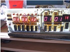
And the photos after that picture show that I managed to get the Exachron working by showing the already past Date, (old programmed date and time in microcontroller) and Time as transmitted by my DCF transmitter. And shown is my in 2007 in flowcode designed 3 time zone DCF 16×2 reciever that displays that same DCF result as proof! (Because taking the photos took a few moments, the time on my DCF reciever LCD 16×2 display already was advanced further in time).
Plus here a simplified view on both 74123 in the circuit that should help to better understand the connections to and from all 4 monostable vibrator chips.
Above the in this article mentioned Antenna Amplifier I also made perfectly working on a experimenter’s board to make sure the Reciever board was working okay. (as from the circuit in my previous article about the Exachron).
And next photo shows the Elektor DCF Time pulse transmitter I built to check the Reciever board. It can be used in 2 ways. By its 77.5 KHz radiowave transmission, or by connecting it with the Exachron reciever input through the RCA (tulip in Dutch) output connector next to the green led. With the dip switches an old DCF transmission test can be selected to test leap year or leap seconds and summer/wintertime, etcetera. For instance the 28 to 29 Feb transfer test if needed.
In conclusion only monostable vibrator potentiometers A and C (pin 13=Q1, pin 4=/Q1, pin 14=Cext1 and pin 15= Rect_Cext1 ) from both 74123s seemed to work. But establishing the function of potentiometers B and D (pin 5=Q2, pin 12=/Q2 , pin 6=Cext2 and pin 7=Rect_Cext2) was very difficult. And because of the very low frequency of the monostable multivibrator output signals, being only around 1-2 Hertz, adjusting them even on my 350 Mhz Tektronix oscilloscope was very cumbersome and didn’t seem to make any change.
If they were digital potmeters we only would have 16 possible combinations to test. Because they are analog, finding the correct calibration is apparently very hard. And without any documentation or even a working and good calibrated second Exachron to compare with, this is close to impossible to manage. And after replacing all bad parts it now only needs the right calibration adjustments. Although I managed to get the Exachron display the correct time, it was unstable most of the times because of the wrong calibration. I learned a couple of new things, especially working with Tina from
Designsoft which also can be very interesting to other engineers too! There are so many technical possibilities to explore in Tina. As I also mentioned in a post after my previous article about programming in VHDL with Free Quartus.
Even when designing components and circuits in VHDL! Although I question their statement that Tina supports unlimited sub-circuits in VHDL. Next everything being limited, simulating the Exachron circuit without VHDL mode was unsuccesfull even where there were no errors, only unconnected pin warnings. The simulation of the complete circuit apparently took too much time, which would require a supercomputer to simulate in real-time. Which would likely be a big speed accelerator because Tina supports multi core processors and is configurable to the taste of the user.
Something that is just another example why Tina is great when designing, programming or exploring electronic circuits or its components. And likely similar or more can be done with Proteus, with costing about $1200 USD last time I checked, is twice as expensive compared to Tina.
Anyway this will apparently be the only and now second existing article about exploring the Exachron time pulse reciever. (1977?). It took a lot of time to explore, and after my article about repairing the DY294 High voltage Semiconductor/e-cap tester my biggest, but I gained many new experiences from it! And that holds more value worth beyond any price.
For completeness sake I also insert hereafter the fully corrected and redrawn Exachron circuit.
And I end by mentioning the words one teacher once said; “It is easier to start making all the connections over, than it is finding the wrong wire”. Which in a similar way it is to find out how
someone else made his design, without any plans or documentation left, now over 40 years ago. I think it was an interesting enough technical resume to read about.
Addendum: Take note that 3 different types of BF245 N-CHANNEL JUNCTION FETs exist. In the Exachron on the reciever board they were of type B. Know that when you buy them that also types A and C exist! By-the-way: the mentioned vertical LED strength meter in the interconnection schematic was not added to the circuit because it was working fine. But it is a simple UAA170 driven LED strength meter on the front right as visible on photos in my previous Exachron article.
All common pins of the twelve 7-segment displays need a Vcc +5V connection like they had in the previous drawn circuits. But in fact the last 2 seconds displays were driven by 7448 ICs which need common cathode 7-segment displays which can’t be simulated yet in Tina, so I used 7447 ICs instead. Simulating 7448 ICs is no problem. After I mentioned this common cathode display problem to the Tina designers, the common cathode displays will be added to a next Tina upgrade. And the R9(1) and R9(2) pins 6 and 7 of the 7490 need to be grounded, which also was correct in previous circuits but got lost while editing to this schematic with new component symbols.
And all 7447 and 7448 /RBi_BO pins may be connected to each other. (but are apparently not connected to any other part of the Exachron circuit).
I also added text to the 6 nicely by Jestine added videos. So in case anyone wants to see the sub-circuit added explaining text, just open the Youtube videolink.
Which also explains the complexity of the route that the DCF_in signal travels through all Exachron components. The DCF_in signal or its frequency in these Seconds_counter Youtube sub-circuit simulations however did not really matter.
Because the 74123 ICs with their four Monostable multivibrators (named A,B for 74123_1 and C,D for 74123_2) are apparently only time calibrated active when the A input of 74123_1_B (with /CLR of 74123_1_A) becomes high. Although DCF_in being “1” or a “0” bit somehow must make a difference for the 4 monostable pulsemultivibrator circuit. Which is hard to simulate without the correct calibration information. Maybe using a 100mS input pulse and a 200mS pulse instead of the 1 Hz pulse used will make a noticeable change in the simulation. But the outcome also than depends on the set value of all 4 potentiometers. And the component values used. Why calibrating is so very hard.
The DCF_in signal is only active for 100 or 200 milliseconds at every second. Except in the 59th second that (when counting 0 to 59 seconds is the 60th or last second of a minute) has no pulse and marks the beginning of any new minute.
The 77.5 KHz DCF radio transmissions also send out a few parity bits in every 59 BCD coded bits of any minute, to be able to check if part of, or the whole recieved code was correct.
My earlier published article on “How to build a DIY fully automated light controlled Fan regulator” was also designed by using the Tina program. And that very successful design still works to this very day without causing any problem whatsoever! Which is one of the reasons why I decided to buy the Tina designer program (Classic version but with the extra HDL option!).
Albert van Bemmelen, Weert, The Netherlands.
Please give a support by clicking on the social buttons below. Your feedback on the post is welcome. Please leave it in the comments.
P.S- If you enjoyed reading this, click here to subscribe to my blog (free subscription). That way, you’ll never miss a post. You can also forward this website link to your friends and colleagues-thanks!
Note: You can read his previous repair article in the below link:
https://jestineyong.com/quartus-ii-web/
 (59)Dislikes
 (2)
(2)
22 Comments
Leave a Reply
Cancel reply


Anthony
May 29, 2017 at 6:25 pm
Hi Professor Albert, that is certainly a lot of technical information you have provided and I will have
to read this article maybe 5 or 6 times or more to try and absorb it. But wow you have certainly
taken on a very complex repair and I salute you for what you have achieved with the Exachron !
Well done and Kind Regards
Anthony
May 30, 2017 at 3:41 am
Every article you write Mr Albert is very useful and interesting because you have great knowledge and
I always look forward to reading them. Thank you for taking the time to prepare and share them
with us here !
Kind Regards
Albert van Bemmelen
May 29, 2017 at 9:41 pm
Thank you Anthony! You are often very quick with posting your much appreciated comment. Like often I have to thank Jestine for taking the time of publishing the big article so well! I only hope to be able to correctly calibrate the Exachron reciever for my friend Charles in time. Also because it already took a lot of investigation, and also money to replace all defect parts, and placing all of them on DIL sockets.
Maybe this article will lead to some valuable answers after it is read by other Exachron owners? And the theory about simulating electronic circuits is surely very useful in other repair cases too.
Des Gilham
May 29, 2017 at 10:45 pm
This type of repair and of course the most helpful comments that accompany them at all times are only always done by what is known in the trade as nutty electronic geeks, without which electronics as such would not exist and most certainly not be as interesting!
Well done with this one!
Albert van Bemmelen
May 30, 2017 at 1:57 pm
Thank you for your kind words, Des Gilham! I would not mind if someone would call me a nutty electronic geek. Because that also could imply that I might excel in something in a good way. As long I'm not doing the same thing over and over again while expecting different results.
Parasuraman S
May 29, 2017 at 10:50 pm
The device in discussion is strange to me. The detailed technical stuff contained in this wonderful article cannot be easily digested by me! May have to read and read and sit chewing the cud for weeks!
Albert van Bemmelen
May 30, 2017 at 2:21 pm
I understand your concern that the device is strange to you, Parasuraman S. And it likely will be for many other readers too. Not knowing how many Exachrons are manufactured exactly or how many have survived after 40 years or more, is the big question. And hopefully someone still owns a service manual with some info on how to calibrate the device after reading this article. But the in the article given theory on how to test single components or sub-circuit parts is in fact very easy and helpful if you try it yourself.
The Tina TI version 9.3.150.4 can still be downloaded freely at for instance:
http://www.softpedia.com/get/Science-CAD/TINA.shtml
I do not know if it offers the same virtual Oscilloscope simulation function, but the used TTL chips used in the simulation are also all about 50 years old. So just give it a try. I'm here if you need any help!
Albert van Bemmelen
May 31, 2017 at 11:40 pm
About the free TI Tina version 9.3.150.4: I just re-checked the program.
The Oscilloscope and other Tools work splendidly, it even has the VHDL (mixed mode?) function and is almost a standard Tina version, but it doesn't animate the circuit in any simulation. And there is no button for it either. Neither is the PCB designer integrated. Nevertheless it does give allmost all else in a Spice way on screen (like my version 10 and 11). Even the temperature calculation and so on, which my 600 euro Tina version does too.
Yogesh Panchal
May 30, 2017 at 3:11 pm
Albert,
Good Info thanks for sharing.
Albert van Bemmelen
May 30, 2017 at 4:53 pm
I hope that the simulation info will also be of help to you, Yogesh. Thanks for commenting.
Gerald
May 31, 2017 at 11:25 am
Hi Albert,
This is a colossal project, thanks for sharing.
I don't have any experience with TINA. Is it good for analogue circuits as amplifiers and oscillators?
I have done some testings with Spice and other simulators but still prefer the real thing like breadboard or Manhattan Style wiring. When you go up in frequency there are extra inductances and capacitances that the simulator cannot see.
But I guess, for digital with the thousands connections 🙂 a simulator is still better.
Cheers,
GM
Albert van Bemmelen
May 31, 2017 at 1:48 pm
Hi Gerald. Of course the not TI (Texas Instrument) 'standard' Tina versions all support amplifiers and oscillators! My bought version 10 (11 upgrade was free afterwards as bonus because version 11 was almost ready at the end of 2016.) even support mixed modes, as well as VHDL digital modes. Plus microcontroller simulations etc. etc. Too many things I have yet to explore! And Designsoft allows the user to use two separate running Tina versions at home for the price of one (plus a one year free TinaCLOUD on-line version, I have never yet used..), so the user can simulate 2 designs simultaneous!
(I also bought a Tina version 11 Dongle version for 30 Euro extra to escape the trouble of having to register on-line which involves long serial key codes. Which make it possible to use Tina on any PC that doesn't have an internet connection. So I guess in a way I'm now able to run 3 Tina designers simultaneous now, but not that I needed it yet). I was a bit disappointed that Tina was not able to simulate the entire Exachron circuit fast enough, even on my quad core desktop pc, but that must have been caused by the four 74122 monostable multivibrators in the two 74123s that slow down the circuit too much.
Albert van Bemmelen
May 31, 2017 at 2:24 pm
About you asking when going up in frequency that there are extra inductances and capacitances that the simulator cannot see? I can answer following, Gerald.
In some of my projects I used one or more push buttons, after which I got very wierd results while running my circuits in the Tina simulator. I therefore had send in my circuit to Designsoft (which circuits are always very small in size compared to other digital files) to get their always very helpful answer. And they told me that the wierd results were caused by the fact that in Tina their property value was set to 1 Giga ohm which they are just like when not ideal.
The user can easily change these component property values to his own preference. But I guess that most components are just given no ideal properties to make their behavior match real components.
Robert Calk
May 31, 2017 at 11:30 pm
Wow, what an article, Albert! Nice work!
Albert van Bemmelen
June 1, 2017 at 11:37 am
Thanks Robert. It also must have been more work than usual for Jestine too. But all for the greater good called Electronics.
suraga Electronics
June 1, 2017 at 3:02 pm
Hello Mr,Albert.
yes Wow..Very well work. best informative
Thanks.. so much!
Albert van Bemmelen
June 1, 2017 at 9:06 pm
Thank you very much Mr.Suranga. I'm glad that most readers understood and liked the article despite the dislikes I seem to get often!
Humberto
June 4, 2017 at 8:35 pm
Hi Albert, do not get sad about the dislikes, maybe some people did not understand well your article. In my own opinion you have done a correct work, very scientific and of course you have dedicated some time to study and redact your nice article. So congratulations Professor.
Albert van Bemmelen
June 5, 2017 at 3:42 pm
Despite the dislikes I believe it indeed was a good informative article. So I am happy about that Humberto. I do not know however if I qualify to be called a Professor, but I humbly absorb your nice comment.
Andrea Del Corso
June 1, 2017 at 9:14 pm
Great man Albert!Yours work is priceless.Thanks for all dedication at the electronics world!
I remember the article on digital tester DY294,which allow me repair my istrument!
Albert van Bemmelen
June 2, 2017 at 6:56 pm
Thank you Andrea Del Corso, nice to hear that I helped you fixing your DY294 tester!
Albert van Bemmelen
June 16, 2017 at 1:32 am
I recently found an artikel in Elektuur (now Elektor) that resembles part of the Exachron circuit. It was published in Dutch Elektuur 137 January 1975 (on pages 5 to 8). The article explains how the MMVs in the 74123 detect the DCF_in signal being '1'or a '0'. And how that information is shifted into the 74164 register.
You can find that magazine and lots of other electronics magazines movies and books on:
https://archive.org/search.php?query=elektuur%20141
And on http://www.americanradiohistory.com/Electronics%20_Now.htm
(completely free!)