
Fender Valve Guitar Amp Repair
I got this beautiful Fender Hotrod deluxe guitar amplifier for repair.

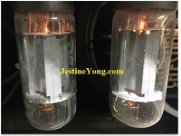
It looked to be in pretty good shape, and is used mainly in a local church. I could see that it still had the original factory installed Fender Groove Tubes. The set consists of 2x 6L6GC power tubes and 3x 12AX7 preamp tubes.
Contrary to popular believe valve amplifiers are still highly sought after in the hi-fi and pro musician communities, especially amongst guitarists. There are however only 3 factories left in the world that produces quality valves. Most of them have been going since the days of WW1 & WW2.
Anyways, powering this amp up revealed some audible hum and some noisy scratching sounds from the speaker.
I opened her up, and could clearly see that the electrolytic capacitors were failing. This can be seen on the positive side of the e-caps. The electrolyte had started oozing out from the positive lead entry point. These caps clearly had reached the end of their life and had to go!
I could also see some coloration on the pcb around the two power resistors.
This is due to heat, and leads to cold solder joints.
Time to remove the board.
NOW A WORD OF CAUTION WHEN WORKING WITH VALVE AMPS!
THESE AMPS CONTAIN LETHAL VOLTAGES, AND THE CAPACITORS CAN STORE A LETHAL CHARGE. DISCHARGE ALL CAPACITORS AND VERIFY THAT THEY HAVE BEEN DISCHARGED WITH A VOLTMETER. ONLY THEN IS IT SAFE TO COMMENCE WORK ON THESE AMPLIFIERS.
First remove the knobs from the potentiometers. Then remove the nuts and washers, including those from the jack sockets. Then remove the pcb screws. Carefully push down on the PCB and the pull it outwards so that you can gain access to the bottom solder side. I marked the bottom of the board with a sharpie so as not to confuse myself when installing the new capacitors.
There are a total of 4 filter capacitors, 1x 47uF 500V, and 3x 22uF 500V. They are glued down onto the pcb. To make removal easier I take an exacto knife and cut the plastic labeling from the caps. Then remove the actual capacitors, and then peel the labeling from the board.
The glue or silicone is easily scraped off the board.
The new capacitors are ready to install. To my dismay I didn’t have the needed 47uf 500V in stock. So I decided to use 2x 100uF, 250V, 105 degrees C, Nichicon capacitors connected in series. This will give me 50Uf, 500V. Close enough!
When connecting capacitors in series, especially in power supply filtering applications, you have to add a resistor across each capacitor to force equal voltage sharing. I usually use between 100K and 500K for tube amplifiers.
Luckily this amp had some extra pads and links on the pcb that I could use to make the two capacitors lie flat on the board.
I then soldered the two resistors to the bottom of the board.
After all the capacitors were installed, I quickly scanned the board for cold solder joints. I reflowed the solder at places, and finally cleaned the bottom of the board with an old toothbrush and some IPA.
I reinstalled the pcb to the chassis. When doing this remember to install and tighten the nuts from the potentiometers and jack sockets first before installing the pcb screws!
I then added some silicone to the caps to keep them in place.
When installing new filter caps in a valve amp such as this one, it is very important to “reform” the capacitors. This ensures that the dielectric is charged up to its full capacity. This is especially important with high voltage capacitors, and if they have been sitting on a shelf in storage for a few years.
To do this, I connect the amp to my variac without any of the tubes installed. I then switch the amp on and bring the variac up slowly in increments of 50V. I let the amp sit for a couple of seconds at each 50V increment, until I reach 230V in my case (230V in my country).
The capacitors are now “reformed”.
Next up, I replaced the tubes with a fresh set. The 2x 6L6GC tubes need to be a matched pair. I prefer matches of 5%. You can buy them matched.
With the new tubes installed, its time to bias the amp.
A lot has been written about biasing, but basically we are again ensuring optimum operation of the output stage. This is a class AB amplifier, and we want the tubes operating in a region were there is no crossover distortion happening.
Luckily on the Fender Hotrod amps, there is a bias test point indicated on the board.
Set your DMM to mV and probe between chassis earth and this point. Adjust the trimmer for a reading of 68mV.
Let it sit there for an hour or so and recheck. Make adjustments if necessary. Here you can see the output waveform with a 1khz input signal with the crossover notch “just” visible.
Lastly I cleaned all controls and jack sockets with some contact cleaner. This concludes the repair of the amp. Tube amps are exciting, and have a sound second to none!
Lets keep the culture alive and remember to “keep ‘em burning” To find out more about tubes and tube amps, check out Uncle Doug’s YouTube channel.
This article was prepared for you by Riaan Diedericks. He runs his own electronics repair shop in Pretoria, South Africa. He specializes in Pro Audio repairs.
Please give a support by clicking on the social buttons below. Your feedback on the post is welcome. Please leave it in the comments.
P.S- If you enjoyed reading this, click here to subscribe to my blog (free subscription). That way, you’ll never miss a post. You can also forward this website link to your friends and colleagues-thanks!
You can also check his previous repair article below:
https://jestineyong.com/chauvet-4-bar-flex-repair/
 (138)Dislikes
 (0)
(0)
17 Comments
Leave a Reply
Cancel reply


Yogesh Panchal
November 17, 2016 at 9:43 pm
Riaan,
Good Repair! Thanks for sharing.
PARASURAMAN
November 17, 2016 at 9:43 pm
Very, very glad to see an article on Valves coming up, my favourite! Very useful and professionally prepared article. Cutting the plastic of capacitors, adding parallel resistors, feeding voltage gradually increasing in steps from a Variac etc. are gems of informations one can get! Learnt a lot! Big salute!
George Greenfield
November 17, 2016 at 10:21 pm
Early in my career everything I worked on was electron tube based. Then along came transistors / solid state. I disliked tube circuits because they were hot, dirty, and dangerous. Well after working solid states for many years, I now prefer old radios and tv type electronics that employ electron tubes. Go figure..
I've come Full circle I guess.
Great repair !
Chris Massie
November 18, 2016 at 2:25 am
Great Article and Sanitary installation! Nice to have a Variable Resistor to set Bias - not so with older amps. Baie Danke Riaan.
Anthony
November 18, 2016 at 2:59 am
Great repair Riaan and a very interesting read with good useful tips by you. Thank you for sharing this article with us
here on Mr Jestine Yong's website. It's not often we see repairs involving valves or tubes these days so thanks for
the trip down memory lane to where electronics began.
Kind Regards
Albert van Bemmelen
November 18, 2016 at 3:49 am
Interesting repair, even for a non-audio engineer like me. The oozing out of elecytolyte from the positive side of the e-caps sounds very familiar. Same thing happens to 10uF 450V e-caps on Quicktronic De Luxe HF 1x56/230-240 1...100% Fluorescent Tube Lighting controller Boards (Made in China by OSRAM). Strange thing is that the 10uF 450V exist in two versions. The e-caps 16x35 sizes
( http://www.ebay.nl/itm/310824249593?_trksid=p2057872.m2749.l2649&ssPageName=STRK%3AMEBIDX%3AIT),
and also the smaller 5mm pitch ones
(http://www.ebay.nl/itm/5x-10uF-450V-Radial-Electrolytic-Capacitor-105C-Pitch-5mm-/181210161876?hash=item2a30f7a2d4&_uhb=1). Last smaller one I haven't tested yet is max 105 Celsius. The bigger e-cap 16x35mm has a max temp of 85 Celsius and a working life of only 2000 hrs.
I expected the larger ones to handle a higher temp compared to the smaller e-caps with the same Capacity and same Max voltage, but it isn't.
Henrique Jorge Guimarães Ulbrich
November 18, 2016 at 4:19 am
Great, Riaan. It took me back to my old, good times, when I not only worked with repair of tube guitar amplifiers: I was a musician too, and used these amplifiers over the stages. Years 60 a 70. Here in Brazil, the amplifiers didn't used 6L6 at the final power stage; the preferred one was EL34.
Mark
November 18, 2016 at 5:45 am
An oldy, but a goody!
Well done on your repair.
Bassbuddy
November 18, 2016 at 6:15 am
Dear Riaan, being a (bass) guitarist, I liked your article very much. I also am a tube lover. My electronic training in the 1960's concentrated mainly on radio tubes.
My first projects also were designs with tubes. I still enjoy a lot working on them.
Arthur
November 18, 2016 at 6:36 am
Good show, well documented, thanks for sharing. Much food for thought!
Gerald
November 18, 2016 at 8:23 am
This is music to my ears Riaan, thanks for sharing this wonderful article and professional repair practices. Tube amplifiers are still preferred by guitar players for good reasons.
Cheers,
GM
suranga Electronics
November 18, 2016 at 5:15 pm
Mr Riaan Diedericks,
Wow.. Nice Repair
Thanks
Lewis Spedding
November 19, 2016 at 4:41 am
Thank you for a fascinating repair read Mr Riaan Diedericks.
You have taken a lot of time & trouble to document your work & expertise.
I have been absorbed reading it today. My interest in repair work has been brought back to life again after a time away
Kathleen Kelly
November 19, 2016 at 6:24 am
Thank yoy, Riaan for including the SAFETY precaution. I'm not yet skilled enough to tackle this project, but I play guitar including a vintage electric guitar and appreciated the tutorial. My fiance died in a burn unit as a result of being electrocuted. The irony was that his father was a master electrician. My Stephen should have known better. We can never be too careful. Thank you for your efforts.
Ulises Aguilar Pazzani
November 20, 2016 at 6:33 am
Mr Diedericks, nice repair
Robert Calk
November 22, 2016 at 3:18 am
Nice article, Riaan. Thanks for sharing it.
Humberto
November 24, 2016 at 1:06 am
A good article, and the images have high quality.