
Harmonics and Distortion

Foreword:
As I enjoy every single article from this blog and don’t do much repair works anymore (except for domestic purposes!) I would like to contribute with some of the things I do. I spent most of my career in electronics, troubleshooting and repairs, then for the past couple of years my interest shifted towards circuits design and experiments, mainly for learning and teaching purposes. The purpose of this article is to demonstrate the relation between distortion and harmonics.
In today’s digital world we tend to forget that our original world is essentially analog. Think about the basic things we measure: voltage, current, power, sound, temperature, pressure, time etc… and try to find one that is not analog… We convert them into digital values, process and store them, transmit them (using analog radio waves) and often re-convert them into analog values. The fantastic advancements in digital electronics gave us all the niceties which are now part of our daily life; Mobile phones, Ethernet, Internet, Digital TV, Computers and CDs are only a few examples. The analog world, however, is still omnipresent in form of input and output signals and, of course, the power distribution and power supplies. It will always be here for a simple reason: our world is analog… Amongst the analog signals we generate, measure and process, one of the most important and the most beautiful is the sine wave.
The Sine Wave
The sine wave is the most basic and purest periodic waveform. Any other kind of periodic signals can be seen as a combination of several sine waves of various frequencies and amplitudes. In a periodic signal, the original sine wave is called Fundamental. The other sine waves composing that signal, each of them a multiple of the original frequency, are called harmonics. If, like me, you are not very conversant with the Fourier Transform, you can demonstrate this by combining graphically several sine waves and looking at the result.
For example you can draw a sine wave of a given frequency (Fundamental). On the same graph you draw another sine wave having 3 times the frequency of the fundamental (3rd harmonic) but less amplitude. Then you graphically add both curves to get the result that will look like the figure below. I did that using an Excel Sheet.
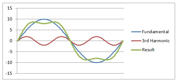
We can see that the 3rd harmonic tends to flatten the top and the bottom of the sine wave while increasing the raising and falling slopes. By adding more of the odd hamonics (3rd, 5th etc…) with the right amplitudes we would be able to create a square wave…
What happens if we combine the 2nd harmonic with the fundamental (instead of the 3rd ):
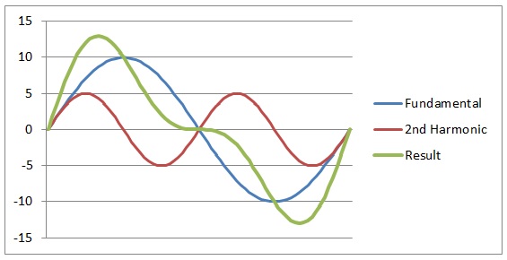
The 2nd harmonic tends to distort the raising and falling slopes of the sinewave. On this example I increased the level of the harmonic signal from 2V to 5V in order to accentuate the effect.
The more harmonics we add, the more distorted the resulted waveform will be. With the right combination of harmonic frequencies and amplitudes you can create a square wave or any other shape. Conversely, starting with a square wave, for example, you can extract the fundamental and all the harmonics by using filters. Some methods for creating a sine wave start with a square wave, followed by a low pass filter to remove all the harmonic frequencies. The quality of the resulting sine wave will depend on the quality of the filter.
This demonstration was to illustrate that distortion can be seen as a combination of harmonics. In the practical life, distortion is created by non-linearities of the components used (transistors, op-amps, diodes etc…). And we measure the harmonics to understand and quantify the distortion.
Odd harmonics (3rd, 5th 7th etc…) are often created because of saturation. Usually when the signal amplitude is higher than what the amplifier can cope resulting in clipping the top and bottom of the sinewave.
Even harmonics (2nd, 4th, 6th etc…) are typically created by an incorrect bias in B and AB class amplifiers. But also by other types of non linearity.
Measuring the Harmonics
One way of measuring harmonics is by using a spectrum analyser. Most modern digital oscilloscopes have this function built in. It is usually called FFT (Fast Fourier Transform) and is just another way of looking at your signal. It is often hidden behind the “MATH” button. Instead of a graphic reprentation of the amplitude vs time it shows the amplitude vs frequency. The horizontal axis shows a certain frequency range (adjustable) while the vertical axis shows the amplitude of your signal. The figure below shows the FFT representation of a 1kHz square wave:
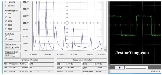
We can see that the square wave is essentially composed of odd harmonics, ie 3, 5, 7 etc…
The next figure shows a sine wave with little distortion:
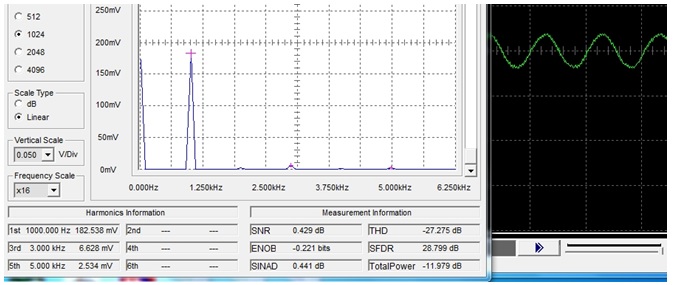
We can see that there are some harmonics here, although of low amplitudes compared with the fundamental. This signal was generated using a cheap function generator based on a XR2206 chip. This is about the best I can get with this particular generator.
The advantage of using a cheap function generator is that we can make it worse… Increasing the amplitude we create a visible distortion and see what happens:
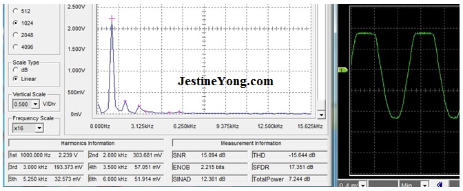
We now see various harmonics with significant levels appearing on the FFT, mainly harmonic 2 and 3.
Measuring the harmonics using FFT is a good way to measure the distortion of an amplifier. It can be useful in troubleshooting stereo amplifiers, by feeding both channels with the same pure sinewave and then measuring and comparing the harmonics at both outputs. This is why you need a “pure” sine wave generator in your workshop…
Generating a “pure” Sine Wave
As much as it is very easy to generate a square wave, generating a pure sine wave can be challenging, depending on the frequency. If you want the frequency to be variable within a large range it becomes even more challenging. We usually distinguish two areas:
– High frequencies for RF applications such as receivers and transmitters
– Low frequencies, mainly for audio applications (AF)
There are too many methods for generating a sine wave to be covered in this article. We will only look at some of the most popular and basic ones.
High Frequencies
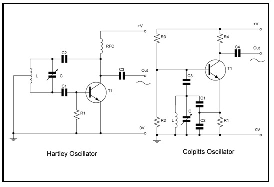
The most popular methods for generating high frequency sine waves are LC resonant oscillators. Inductors and capacitors are combined in a resonating circuit that produces a very good shape of sine wave and has a quite good frequency stability. The main distortion could be created by the non linearity of the components used to sustain the oscillations. Two very popular LC oscillators are the Hartley and Colpitts oscillators, with all their variants. The figure below shows the basic Hartley and Colpitts circuits.
The frequency can be tuned by using either a variable inductor or a variable capacitor. Variable inductors are things of the past and have never been very popular, therefore variable capacitors used to be the way to go. They are bulky, expensive and difficult to find in today’s market, therefore now replaced with varactor diodes. However, varactor diodes have a limited tuning range and, in some conditions, can create distortion (non-linearity again…).
More modern methods for generating frequency variable sinewave include Phase Locked Loops (PLL) and the, now very popular, Direct Digital Synthetizer (DDS). This, however, is a new subject, too big to fit into this article.
Lower Frequencies
At low frequencies such as audio frequencies (AF) the values of L and C needed to produce a resonating circuit would be too large and bulky to be practical. Therefore resistors and capacitors are used in RC filter type combinations to generate AF sine waves. However it is more difficult to produce a pure sine wave shape using RC circuits than LC circuits. There are dozens, probably hundreds of circuits for audio sinewave generators but certain “old warriors” are still favourite and the basic circuits haven’t changed significantly since they were built with vacuum tubes. One of them is the Wien Bridge. The figure below shows the principle of a Wien Bridge:
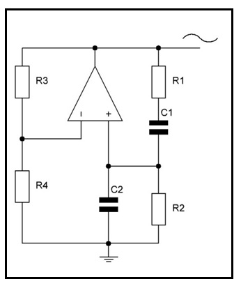
R1 must be equal to R2 and C1 must be equal to C2. The frequency is normally adjusted by using a dual potentiometer for R1 and R2 rather than a dual variable capacitor. Nevertheless the most challenging part of this design is the stability of the gain, set by R3 and R4. If the gain is too high there will be saturation. If too low there wont be any oscillation at all. This design must be improved by adding some sort of automatic gain compensation. Earlier and very popular designs used a small light bulb replacing R4 and acting as a PTC. The correct type of light bulb, however, is difficult to find and the current needed to bring the bulb filament just before the glowing point is too high for modern designs which usually compete for low power consumtion. Current designs opt for a feedback circuitry using a JFET transistor in order to stabilize the gain.
I built a small Wien bridge to demonstrate this:
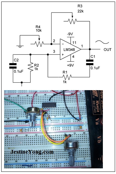
Replacing R3 and R4 with potentiometers allows for tuning the gain. The adjustment is very sensitive and, obviously, we would need an automatic gain adjustment for this circuit to be practical.
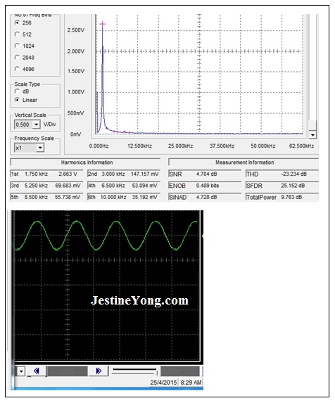
At first glance, the sine wave looks good but the FFT shows a small amount of harmonics, mainly harmonic 2. This is probably because the oscillation is very close to saturation and could eventually be improved by using an automatic gain control.
As much as we try, generating a “totally pure” sinewave is not a simple job. We can find a huge number of alternative ways on the Internet, each of them having their advantages and disadvantages. However, the bottom line is that using the FFT for measuring the distortion is a nice and easy way.
May your amplifiers aways amplifiy and your oscillators always oscillate and not the other way around…

Gerald Musy
Penang, Malaysia
Please give a support by clicking on the social buttons below. Your feedback on the post is welcome. Please leave it in the comments.
P.S- If you enjoyed reading this, click here to subscribe to my blog (free subscription). That way, you’ll never miss a post. You can also forward this website link to your friends and colleagues-thanks!
You may check out his other article below:
https://www.jestineyong.com/linear-power-supplies-and-regulators/
 (97)Dislikes
 (0)
(0)
17 Comments
Leave a Reply
Cancel reply


Robert Calk
April 28, 2015 at 10:27 pm
Nice article Gerald, thanks. I'll be glad when I can get a good digital scope.
Gerald
April 29, 2015 at 11:48 am
Hi Robert,
Thanks for your positive comment. I am also looking for a good digital scope but my budget is limited. For this article I used a USB scope that I bought in Australia a few years ago. For low frequencies it still does the job but my place is plagued with some kind of interferences that also appear on the bench oscilloscope (ATTEN ADS1102CAL). In this respect I got better pictures from the USB scope. As I am going to move house in a couple of months I don't worry to much. I would look at the latest models of USB scopes, they made a lot of progresses in this area recently. And good for teaching and presentations.
Cheers,
Gerald
Robert Calk
April 29, 2015 at 6:08 pm
I want one that is capable of 500MHz. They start getting expensive when you go over 100MHz.
Henrique Ulbrich - Brazil
April 29, 2015 at 12:17 am
Thanks, Gerald. Surely a very, very didactic text. A clear explanation, allowing us to really understand such an important subject. I'll wait for other good articles.
Gerald
April 29, 2015 at 11:56 am
Muito obrigado Enrique pelo seu positivo comentário.
Abraços de Malásia.
Gerald
Igor Levin
April 29, 2015 at 12:44 am
Very useful article, educational. I can add, that simple way to have an automatic gain control is using the bulb in feedback.
And to see the real amplifier distortion you have to use the sguare input signal, because deep feedback will show you good picture for periodical sine signal, not for an impulse one.
Gerald
April 29, 2015 at 4:01 pm
Hi Igor,
Thanks for your input. Yes many people on the web are adamant that the bulb is a much better way, better than the JFET feedback. However they specify a type of bulb that I cannot find here (seems to be common in America though). I could have tested a few bulbs that I have here but my interest drifted towards another project... maybe one day I come back to it.
Cheers,
Gerald
Paris Azis
April 29, 2015 at 1:48 am
Hi Gerald,
I fully agree with the spirit of your foreword.
There are no digital signals in the entire natural environment we live in. Furthermore, all living animals, including us the human beings, use "analog sensors" in order to taste, smell, hear, see, feel the temperature of the environment e.t.c...
The use of digital signals (a wonderful technology in its own indeed, another achievement of the human mind among many others) practically it is used in order to represent these analog signals of the nature with the maximum accuracy. And this is due to the fact that (this reproduction of the original analog signal) is easier to be performed by the use of digital technology...
Of course the languages the various computers or controllers "speak" and "understand" is always digital, but this is only an exception to the rule. And the rule is the reproduction of the original analog signals in their highest degree of accuracy.
Nice and interesting article indeed. Thank you for your effort.
Best Regards
Gerald
April 29, 2015 at 11:59 am
Thanks Paris for your positive comments. I Really appreciate your feedback and agree totally.
Cheers,
Gerald
malamig
April 29, 2015 at 7:20 am
This is a very nice topic! Thanks Gerald.
Gerald
April 29, 2015 at 12:00 pm
Thanks Malamig. Appreciate your feedback.
Henry
April 29, 2015 at 7:27 am
Gerald,
Very interesting reading. I like the scientific angle and analithical approach in your articles. It adds some depth, provides substance and gives better understanding of the operation and/or behavior of the circuitry. We all love good description and handy tips for repairs of various electronic items but the articles like yours also broaden our knowledge and our abilities to recognise reasons when the failure occurs. Thank you for this and keep up with the education we all benefit from.
Gerald
April 29, 2015 at 12:05 pm
Thanks Henry for your positive comments. Your feedback is always appreciated.
Cheers,
Gerald
Humberto
April 29, 2015 at 8:02 pm
Another good and scientific article. Congratulations.
Gerald
April 30, 2015 at 3:54 pm
Thanks Humberto
Parasuraman S
May 1, 2015 at 8:43 pm
Very informative, practical, article which I think is first of its kind. Many thanks for this valuable info. May God bless you!
Taring K Arioka
May 2, 2015 at 1:44 am
Very nice article. I really like it. Thank you for sharing