
HomeMade Testers Were Used In Testing Power Supply Components
This repair was put aside for a long time when I was unable to fix the not working Fan. After I had tested all semiconductors and components, including the e-caps before. Until today when I reopened the unit for another check! And maybe for the 3th or 4th time!
The Fan itself was working fine but it never started in this Corsair VX450Watt power supply. And although I managed to get the Fan running by heating up the components on the mainboard it never worked on its own. The Fan only worked when I heated up the transistors in the circuit around Q901 and R901. But they checked all fine when checked with my DCA75 and other semiconductor testers. But I will come to that later because when I rechecked the already previously made photos I noticed something odd I had not checked before! (remember that this is an important break-through in fixing this Power unit!).
This power supply was given to me because it failed working correctly in the desktop computer of my friend’s neighbor. And all my Power supply Testers tested the output voltages of the Power supply being correct. Only the -5V led on the testers doesn’t work simply because the Corsair doesn’t produce any -5V output voltage.
I even made a special TL431 tester that also can test the optocouplers at the same time and tested the TL431 with that fine tester to make sure my other TL431 testers were all giving the correct same good results! And this repair will show all steps I took to successfully fix the not working Fan.

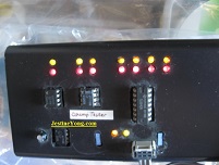
Following photos show the results as given by all my power supply testers (3 of them!) I have that confirm that all outputs are working splendidly. So they do not check on the not working Fan in the unit and are no help in fixing the still not safely working Corsair VX450W!
Previous photo above showed my third and latest power supply Tester. And the already rotating Fan after I managed to fix the not working circuit this repair is about. Only the -5V led never works because the Corsair as mentioned doesn’t have a -5V output.
Next photos show the 12V Fan connector next to Q901, R901 and the other transistors, plus the solder side of the board. I had previously tested ALL semiconductors plus the e-caps including the SS8050 transistors Q901 and resistors that all checked out being okay. Including the semiconductors on all Cooler plates, which are always the easiest to check by removing the entire Cooler plate from the board for further inspection. (so without the need having to remove each and every single semiconductor from the plates at all! And so saving much time when placing them back into their positions on the board). I marked the transistor position Q901 by a blue circle and will now explain why I before wasn’t able to find the culprit why the Fan in this Power supply still wasn’t working.
Therefore I will show some of the previous made photos I took after I had checked these semiconductors before. And please notice the very low Hfe value on my DCA75 Tester of only 18! Something I previously had overlooked! Today in a hunch I remembered not having checked these values at all! So I compared the value I had a snapshot taken from with the values in the SS8050 datasheet. The minimum Hfe value should be about 45 which it never was! And because they normally are much higher I removed Q901 for another check now many months later! And you probably guessed it. The transistor was no longer working and had became a diode! Why I removed it and immediately replaced it by a new SS8050 40V 1.5A transistor.
You can click on the above picture to access the Datasheet
In the next photos the 8050 Q901 position is shown. The HY-510 chip on the vertical board is for modern energy control purposes and so has nothing to do with our not working Fan. After Q901 was replaced which was the hard to find culprit, the Fan finally worked at once!
Previous last 2 photos showed Q901 then and now! Gone from a ‘working’ transistor with Hfe 18 to a BaseCollector diode. (emitter contact is no longer working!).Probably because the max CBO voltage is 60V opposed the the lower max 25V of the CEO of this 1W transistor.
Below the perfect working TL431 + PC817 optocoupler tester I made and used to check the TL431 on the board of this Corsair VX450W supply. It can be found in one of the many Youtube videos and the 3 leds, Blue, Green and Red show a right working sequence when the optocoupler and the TL431 under test are working fine while we turn up (and vice versa down) the input DC voltage between the + and 0 (gnd) connections.
And next photo shows my Elektor Opamp tester I made and use to test single, dual and quadro Opamps. (All at the same time under test if needed!). It can’t test the special Comparator Opamps that exist but a lot of Opamps if not almost any of them.
The last photos show the component side of the Corsair VX450W. And the entire board solder side.
Conclusion: never expect any measured value to be in their in the datasheet given range! It could have saved me a lot of time in finding the culprit! I now was only able to find the cause because I rechecked my previous findings.
Albert van Bemmelen, Weert, The Netherlands.
Please give a support by clicking on the social buttons below. Your feedback on the post is welcome. Please leave it in the comments.
P.S- If you enjoyed reading this, click here to subscribe to my blog (free subscription). That way, you’ll never miss a post. You can also forward this website link to your friends and colleagues-thanks!
Note: You can read his previous repair article in the below link:
https://jestineyong.com/braun-carestyle-3-steamgenerator-iron-repair/
 (91)Dislikes
 (0)
(0)
18 Comments
Leave a Reply


beh
August 28, 2019 at 8:59 pm
Hi Albert
yes, you did it. Hfe is a very important factor in transistors that we have to be very careful about that. I have the same problem in one telephon that smd transistor is not open and not short but the Hfe is low since I could not find any replacement still is not repaired. congratulations in this finding
cheers
beh
Albert van Bemmelen
August 29, 2019 at 2:01 am
I finally did Beh! But I almost gave up on the not working Fan until yesterday.
But now this is fixed I noticed another strange problem when testing these S8050 in my DY294 tester.
I noticed something very odd about testing the CBO and EBO max breakdown voltages because I was unable to determine the limited breakdown voltage of my in the Corsair VX450W repair used S8050 NPN transistor.
Maybe it is something that can be explained? Because strangely both the CBO and the EBO voltages exceeded any of the in the datasheet given maximum voltages. Although I in my repair wrote that the higher CBO was about 60V and the lower EBO only about 25V, my DY294 showed in both VCBO and VEBO tests unexpectedly the max 1630V DC although my DY294 display probably began flickering while I was pressing the test button down longer.
Only the CEO voltage my DY294 gave was splendidly 26V as the 25V given in the datasheets.
I also tested the Iceo by pressing the test button and got 1574uA on the 2000uA scale test. (IMPORTANT!: many DY294 users are unaware that these I ampere current tests can destroy the weaker diodes/triodes instantly because they get hot without even having to press the test button during these other Hfe selected current tests. And any DY294 user should only use these test for a very short period. Any longer test easily results in a steamy hot overheated semiconductor, possible even smoking hot! Especially when an external 3A 6V power adapter is used.).
And to make sure my transistor wasn't destroyed after the tests, I tested the NPN in my other digital testers which showed a perfect working NPN with a Hfe of 293 and a Uf of 629mV.
I have no idea what is the correct explanation behind these very high breakdown CBO and EBO voltages of the S8050 NPN under test? In these tests we only use the same Collector and Emitter testcontacts of the DY294 while pressing the button on the 200V or 1000V scale selection like is explained in the manual. (also other transistors are giving a very high breakdown voltage! But not all of them are behaving this way. Maybe it has got to do with not reaching the max 1mA avalanche limited current of the DY294? But still they often very much deviate from the in the datasheets given max breakdown voltages).
Robert Calk Jr.
August 29, 2019 at 8:54 am
Albert, test that transistor that your other meters say is not damaged by your DY294 with a VOM(with X10K), and see if it passes.
If a transistor, FET, diode, etc.. passes with my other meters but fails with my VOM, I will believe my VOM every time!
Albert van Bemmelen
August 29, 2019 at 8:16 pm
Addendum: I repeated above breakdown voltage tests on my new S8050 Bipolar NPN transistor with both my perfect working DY294 Testers to make sure they both were working fine and are giving the same results which they did!
So it must have been a bad transistor pincontact that previously lead to not reaching the correct breakdown voltage on the 200V and the 1000 (over 1600V!) testscales.
Now I got even better results than those given in the datasheets (depending on the manufacturer the voltages are often not the same) and I got normal acceptable values!.
So as in the manual is written just use only the E and C connections on your DY294 Meter/Tester to test the BREAKDOWN voltage of any Diode/Triode, and connect in case of a NPN triode like my 8050:
1. For the Vcbo (collector-base) breakdown voltage test, simply connect the Collector of the transistor to the C onnection on the DY294, and the Base of the transistor to the E connection of the DY294.
2. For the Vebo (emitter-base) breakdown voltage test, connect the Base to the E connection of the DY294, and the Emitter to the C connection of the DY294.
3. For the Vceo (emitter-collector) breakdown voltage test, put the Emitter on the E connection and the Collector to the C connection of your DY294.
And press the test button on the 200V or 1000V scale selections to read the breakdown voltage on the display. The breakdown voltage normally kills any semiconductor but in our DY294 its is a protected voltage test which doesn't destroy your transistor/diode (or capacitor)! But never touch any wires of contacts while pressing the test button!
In case of a PNP transistor you need to reverse the Base and Emittor transistor connections because the current (the arrow in the emitter symbol) flows in the other direction.
There is also a 4th Breakdown Vces test but that is only a Vceo test with the base connected the the emitter.
My DY294 testers gave a Vcbo of 81V (30,40 or 45V depending on what manufacturer), a Vebo of 11V (5, or 6V depending on the manufacturer), and a Veco voltage of 26V (25V in most datasheets).
So everything works as is to be expected! Problem solved.
Justice
August 28, 2019 at 9:30 pm
Yes Albert this is a complex article yet interesting so much and highly informative, thanks keep it up.
Albert van Bemmelen
August 29, 2019 at 6:16 am
Thanks Justice for your words of appreciation. In case you wonder why I did remove all cooler plates with the semiconductors on them, when all outputs voltages already tested working splendidly on 3 testers you may ask? That was because I was looking for the temperature sensor that maybe was the cause of the not working Fan. But there apparently was no standard temperature sensor on any of the plates and neither on the powerboard as far I could see. So I was looking for something that was not there and that was neither the cause of the failing Fan. So that also could have saved me a lot of time if I had known. But I finally fixed it and it will sure make a difference next time!
Christopher Massie
August 29, 2019 at 12:29 am
Good persistence and lots of dreams at night to alert you and lead you through the process in your subconscious! Intuition is a beautiful thing Albert. Hard work makes it happen.
Great job and thanks for sharing!
Da!
Das Allerbeste,
Chris
Albert van Bemmelen
August 29, 2019 at 4:33 pm
This repair indeed took some valuable time to solve the nasty Fan problem Christopher. Luckily it didn't make me sleep any worse. Now that it is finally fixed does help of course! Our gut feeling can help many times, but in this case I was glad that I still kept that months before taken old snapshot with the measured Hfe 18 on it which was the key in solving the problem. Cheers!
erik
August 29, 2019 at 3:40 am
if you know the type you can search to the equivalent type
Albert van Bemmelen
August 29, 2019 at 3:56 pm
Indeed, but why would you look for an equivalent transistor if you have the exact type in store with the same pin connections. 100 new S8050's only cost about 1 Euro/dollar free shipping!
Imoudu Onwumah
August 29, 2019 at 5:15 am
Please can you let me know what is hfe .I have a board with shorted 8050 trans to repair and I am a beginner in electronics repair .
Albert van Bemmelen
August 29, 2019 at 3:43 pm
That is easy to explain but only if you know how a transistor works Imoudu.
It is the multiplication factor of the current through the collector compared to the much lower current that goes through the base (Ib) of your transistor to make the higher Ic (collector current) possible. And the emitter current is the [ Ib times the Hfe factor plus 1 x Ib ] current. So a Ie current of Ib x (Hfe+1). Your shorted transistor doesn't have a Hfe or neither a good Ib, Ic or Ib current anymore because it only conducts a shorting current. You have to replace the internal shorting 8050 by a good intact 8050 that still works by giving a decent Ic and Ie current after it receives a small Ib current on its base. Transistors normally are current amplifiers. Mosfets are controlled by changing voltages on their gates (base of a Mosfet) and so are voltage switched amplifiers. Processors contain millions of tiny mosfets and the faster they all change from on state to going off the hotter your processor gets! And they only consume energy when their situation of being an open connection or a conducting mosfet changes.
Robert Calk Jr.
August 29, 2019 at 8:43 am
Good job, Albert! A VOM(with X10K) would have found the culprit quick and saved you some time and grief.
Albert van Bemmelen
August 29, 2019 at 3:50 pm
I'm afraid that it was not as easy as you think it was Robert. Because the transistor worked at first as a transistor, but just badly with a too poor Hfe, and it probably only died months later when I heated the board to check if it would start the Fan. (in my search for the temperature sensor that wasn't there).
Parasuraman S
August 30, 2019 at 5:20 pm
Saw the article only today, as Jestine Yong's newsletters are not reaching me for sometime now. A very interesting article with a lot of knowledge and experience shared. Yes, inspite of our advancement in technology, a transistor is still a challenge! Very complex article and throws open multifarious doors of knowledge! No words can appreciate your work well!
Albert van Bemmelen
August 30, 2019 at 9:33 pm
Thank you dear colleague for your too kind comment! In the past sometimes Jestine's newsletters turned up in my 'unwanted mail/spam box'for some reason. But after I placed them back in the 'mail inbox' they again always are received without any problem. The transformer coil repair tips you gave in the comments after your recent article sure will come in handy in case it is the transformer that is defect. But I'm glad it was just a gone bad transistor. I wouldn't know how to easily rewind a transformer coil anyway, and dismantling any transformer core isn't easy I guess?
Parasuraman S
August 31, 2019 at 5:51 pm
The appreciation what you get is a deserving return or rather 'fringe benefits' in the profession.
The transformer rewinding depends on whether it is Ferrite Core or Iron Core. Iron core can be dismantled easily, but not Ferrite. It might break, as it is fixed with glue. We may have to go for a similar former. Coil can be wound by hand. But you should take length and gauge of wire removed for exact replacement. (Not number of windings)
nzero
April 12, 2025 at 12:41 am
It is a manufacturer or a designer mistake to use this type of transistor in this circuit (I mean Q901). Googling 'Q901 Transistor PSU' i have found that others had the same problem with this transistor. For example: https://www.badcaps.net/forum/troubleshooting-hardware-devices-and-electronics-theory/troubleshooting-power-supplies-and-power-supply-design/60048-antec-earthwatts-ea-430-and-ea-500-%E2%80%93-an-easy-bad-caps-fix
The main purpose of this transistor is a classic linear voltage regulator for a PSU fan depending on thermal sensor. Thus it dissipates around 0,9 Watts on average fan speed, which is too much for TO-92 package. It is better to replace it with something more powerful like BD139 in TO-126 case.
I had the same problem, so i drilled a hole in the secondary circuit heatsink and installed BD139-10 here. It has a plastic case, so isolating is not needed.