
How To Repair LG Microwave Oven Not Heating
This LG microwave oven MS-1921HE belongs to my cousin, and during our family visit to their home, his wife told me that it was not heating up, though it was getting on and rotating (runs but doesn’t heat). So I brought it home to fix it.

As usual, opened the cover and did a thorough cleaning of inside with blower and brush. Some dirt on the caps and in some inaccessible areas was stubborn and inseparable!
Brought it on to my work table and first discharged the high voltage capacitors. Then checked for loose contacts, fuse, door switches, mechanical rotary switches of temperature and power, continuity on primary, secondary of High Power Transformer, and ESR of Capacitors. All were ok. So removed all connectors one by one, cleaned and lubricated and refit these back in its place.
Took the Oven to my kitchen, as I do not have a 15A connection on my bedroom converted workshop. Checked and found that the oven was getting turns on and rotating but won’t or doesn’t heat up at all. Brought it back to my work table, discharged the caps.
Then removed the connector to the Magnetron and connected a fuse wire across the high voltage connector pins that come out of the secondary of the transformer. (This was an idea given by my techie friends)
Took the oven to Kitchen, connected the mains plug and switched on. The wire got red and blew, indicating that everything was ok until that point, and the problem was indeed in the magnetron. (Caution: This portion of the output handles around 5000V! So, we need to be extremely careful in doing all these) So carried the oven back to my workshop and removed it.
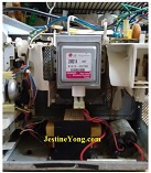
The Model number of this Magnetron is 2M213, and mounting clamps were on the front. We need to buy a replacement matching exactly as per its mounting and high voltage connector. Got 2M214 instead of 2M213 and I learnt from my friends that it was ok. Connected the new magnetron.
Checked all connections once again, carried the oven once again to my kitchen, put some quantity of water in a microwave safe plastic container and switched the oven on. The mechanical switches are manual. The power switch has to be turned to select the desired watts. The timer switch has to be turned to the desired time written on the dial. Then the oven will get on, and the knob of the switch will start retracting to zero slowly, for which there is a spring coil inside like in old time wall clocks.
Same mechanisms can be found in some semi-automatic washing machines also. This switch has also got a bell fit on it, once it reaches 0, and a lever is pushed to sound the bell, like a cycle bell. (Please see the picture above). The oven worked well and the water kept by me for test boiled.
Switched off mains, removed the hot vessel and brought the oven back to my workshop. Put the cover back and did a thorough cabinet cleaning. Look at the oven now to see how it shines like new and ready to cook food again!
Another job completed satisfactorily!
This article was prepared for you by Parasuraman Subramanian from India. He is 66 years old and has more than 30 years’ experience in handling antiques equipment Valve Radio, Amps, Reel Tape Recorders and currently studying latest techs classes conduct by Kerala State Electronics Technicians’ Association. He was a BBA graduate, retired as MD of a USA company.
Please give a support by clicking on the social buttons below. Your feedback on the post is welcome. Please leave it in the comments.
P.S-If you enjoyed reading this, click here to subscribe to my blog (free subscription). That way, you’ll never miss a post. You can also forward this website link to your friends and colleagues-thanks!
You may check on his previous repair article below:
https://jestineyong.com/crt-tv-repair-flyback-replaced/
You may also check on the article about Microwave Oven repair by Humberto and Sam:
https://jestineyong.com/faulty-big-capacitor-in-microwave-oven/
http://www.repairfaq.org/sam/micfaq.htm
 (130)Dislikes
 (0)
(0)
39 Comments
Leave a Reply
Cancel reply


Yogesh Panchal
July 15, 2016 at 2:32 pm
Good job! sir.
Want to know about these type of high power capacitor Discharging technique. (without shorting the capacitor terminals with screw driver)
Parasuraman S
July 15, 2016 at 6:58 pm
Did Screwdriver shorting. I have no idea whether the two resistor discharging method suggested by Justine Yong can be used in this. I have no other ideas about this.
Henrique Jorge Guimarães Ulbrich
July 16, 2016 at 4:39 am
As far as I know, these HV capacitors have internally a resistor connected in parallel, in a value enough to discharge the capacitor in a few seconds. In case of maintenance, one can discharghe it in advance with a screw driver, without causing damage to the surrounding components.
Beau
July 16, 2016 at 9:01 am
I have a 100k 25 watt resistor that I soldered between two alligator clips. One clip I ground on the edge of the cap and the other I attach to a screwdriver. I then touch each terminal for a couple of minutes to discharge.
Albert van Bemmelen
July 15, 2016 at 2:46 pm
Thank you for the article Parasuraman Subramanian.
I have a question though: why would you need to check the HV Transformer output with a Fuse that then blows? Because there already is a HV Fuse (5KV 0.8A) in the secondary of this transformer circuit in case the HV 2100V Capacitor, The HV Diode or the Magnetron Tube itself short to Ground. And of course there is also the Primary Glass Fuse 32mm (About 15A). And it probably also protects the circuit in case the 3V (10A?) Filament in the Magnetron Tube shorts too. The 2100V Capacitor in combination with the HV Diode make together a about 2 x 2000V = 4KV HV Voltage that is going straight to the Magnetron Tube. In case that Voltage is Shorted the HV Fuse will blow. And both Diode and Capacitor need to be replaced because they both can incidentally produce an internal Short circuit, if it is not the Tube that is shorting (which can be measured from Tube connections to Ground). The HV Capacitor does have a 10M internal discharge Resistor, so discharching only needs to be checked with a 2KV Volt Meter. I always close the Magnetron Metal case completely before I test it, just to be Safe and I take it you did the same?
Parasuraman S
July 15, 2016 at 6:52 pm
Magnetron is the load. To isolate stage of fault, this method is used. If the fuse wire blows, all is well up to that point. If not we have to check all other sections before that. It is to make troubleshoot simple, that is all!
Albert van Bemmelen
July 15, 2016 at 9:28 pm
It is still unclear dear Parasuraman S to me how and why you should blow a Fuse for that test. See also the remark of Waleed in the Post below.
Albert van Bemmelen
July 15, 2016 at 11:55 pm
PS: there are other ways to test if the Transformer is BAD and it won't cost any Fuses nor this rather dangerous test. See : http://www.microtechfactoryservice.com/xformer.html
or the components Test Page on this link:
http://www.applianceblog.com/mainforums/threads/6623-Kenmore-665-60659000
Cheers (; )
Henrique Jorge Guimarães Ulbrich
July 16, 2016 at 4:58 am
The method suggested for this purpose (that I use without problems) is as follows: disconnect the filament plug and then power on the set. With a screwdriver in contact with the metalic part (chassi) of the MW oven, bring the tip of the screwdriver closer (without touching) to the filament connector (or a portion of wiring connected to it). Let us say, 3 or 4 millimeters. If there is high voltage (4 kV), an arc must occur. As this happens, turn-off immediatelly in order not to damage the surrounding components. The problem must then be a faulty magnetron. If there is no high voltage (no arc), the magnetrom must be OK, and the work shall be focused in the circuit that generate this HV (transformer, HV diode or the HV capacitor. Of course provided that mains voltage is applied to the big transformer.
Albert van Bemmelen
July 16, 2016 at 6:12 pm
Thanks Henrique Jorge. Your explanation is excellent! Still it seems a dangerous and avoidable way to test and 'really see' if the HV circuit works. In the meanwhile creating the possibility like you said to destroy something that was not defect before. And I never had a bad Magnetron Transformer myself before either.
I think there is a much better and safer way to check if the HV circuit is okay. In the CRT Television repair days it was possible to test the precense of the HV Transformer Output by simply holding a small Neon LightBulb near it. Because the noble Neon Gas Lights up around 80 Volts no galvanic connection or LightBulb Wires are needed either. I have not tested this with any Magnetron myself but I think it is a better and safer way if it works. And if any arc still does destroy anything at all, it probably only will be the little Neon Bulb.
Henrique Jorge Guimarães Ulbrich
July 17, 2016 at 7:13 am
Thanks Albert for your contribution. Concerning the way of test you've described, I do agree that it's really more safe. I only have a doubt: in CRT sets, the high voltage is about 15 kV or even higher. In a microwave oven, the voltage is around 4 kV. Indeed, there is an expressive difference between these two voltages. In CRT sets it works, but there is a doubt if it will work with the Magnetron circuit. As you've said, you have not tested this with any Magnetron circuit. Once proven that it also works, perfect. Another improvement in our knowledge of maintenance.
Paris Azis
July 17, 2016 at 11:08 pm
Hey Henrique
This does not matter at all. The high voltage test probes used for these measurements in TV,CRT anode voltage etc,can be safely used here as well. They simply will measure much lower voltage. One way or another, they were resistive dividers and I don't see why they could not be used here,in measurements on MW transformers.
Albert van Bemmelen
July 18, 2016 at 12:32 am
I know Paris, but buying them really isn't cheap. I know that there
was an article in one of the Everyday Practical Electronics Magazines
to build one yourself. But normally I never need any HV Probe and I
mostly work way under any High Voltages in my own electronics projects.
I once opened a defect HV Probe though at my work at Philips Medical
Systems and managed to repair the Probe that was thrown away. It had one or two very long (76mm !) Blue coated High Ohmic (650 Mohm !) Resistor(s) inside the probe that had one of the legs broken of.
After attaching it to a thin wire and adding some special superglue to it I got it like new working again. But that was until my colleague lateron had injected it with some special Molding Rubber that destroyed it. (These Probes originally are free from any additions inside. Only Air).
Paris Azis
July 17, 2016 at 11:31 pm
Hi Albert
In CRT TV we deal with high frequency pulses which are much more easily detected with a neon lamp, even from a remarkable distance away from the core of the transformer. With a normal,low frequency transformer,although of high voltage as with these of MW ovens, I am not sure if it works. In any case I don't consider it a safe test to perform,due to the much elevated power available in these cases. Personally speaking, I would build a resistive divider for this purpose. It is just a direct application of Ohm''s Law, provided that all proper measurements are taken as regards safety against high voltage backward leakage.
Albert van Bemmelen
July 18, 2016 at 1:34 pm
Thanks Paris. I also read your interesting Transformer test by using a Variac. Of course we need probably a bigger Variac to be able to test these higher Magnetron Transformer Powers.
And I have a question that I best ask you since you are an expert in repairing and building Transformers: Is het possible to build a very big and dirt cheap isolation transformer by just using two Magnetron Transformers connected with each others Outputs together? Or am I asking a stupid question? (of course with the safety HV and other Fuses in the circuit). Thanks in advance for your valued answer!
Paris Azis
July 18, 2016 at 5:35 pm
Of course you can Albert. Connect the high voltage windings with each other and then use one of the primaries as input and the other as output. You only need to take care of two things. First and most important is to secure proper isolation against any leakage of the secondaries to their external environment. The second thing is to use exactly the same type of transformers, for proper matching of the coil impedances. Just for safety reasons alone, it would be wise to use proper fusing in this construction. I would use the high voltage fuse as well, as an interwinding protection, along with an input fuse for the mains supply.
Paris Azis
July 18, 2016 at 6:00 pm
Albert,
In addition to all above, you don't need a huge variac for the recommended (no load) test. The idling current of the transformer in this case is under normal conditions very low in comparison to its full load one. And this depends upon its overall losses or else upon its quality as a product.
Even in the event of fear for working with high voltages while a variac is not available, the "poor technician's"-safe method would be to feed the transformer backwards, i.e. to supply the input mains voltage in the secondary winding and (quite safely) to measure the output developed at the primary. This also obeys the the rule of the windings ratio (or better said the ratio of their turns, or,finally, the ratio of the primary to secondary voltages). So, if the output doesn't respond to the one expected per the voltages ratio, it would reveal a transformer defect immediately. This is my preferable testing method for cases like the one of this article.
Albert van Bemmelen
July 19, 2016 at 2:00 am
That is what I thought but you assured me it should work, Thanks Paris!
Power Secondary Coil is induction Power Primary Coil of the Transformer. Current Primary Coil times Input Voltage equals the Induced Secondary Coil Voltage times Current Output (and vice versa). 4KV x 0.8A (Max) +
3V x 10A should make a Transformer of about give or take 3200 Watt + 30 Watt makes 3230 Watt of Power. Except we use two Transformers in line (Output to output) so I take it that the total Power of such a Isolation Transformer would decrease because of it?
Paris Azis
July 19, 2016 at 1:50 pm
Albert, you will get the nominal VA power of the indidual transformer you use minus the losses. There is no other problem. This connection of transformers is the one the power plants distribute their generators power into the grid. First they step up the voltage to be sent in long distances where it will be consumed after stepping it down to the usual nominal grid voltages. There is no difference in the application you intend to apply. It's absolutely normal. It only needs the proper precautions along with more space than that needed for a single isolation transformer of the same wattage. That's all.
Paris Azis
July 18, 2016 at 12:07 am
Hey Parasuraman
Interesting repair,nicely presented as well. As regards the transformer test, apart from the method I mention below, there is another one, equally easy and safe. It only needs a small power variac. You disconnect the magnetron,which is your load, and have the secondary winding of the transformer free. Then, you feed it through the Variac starting from zero volts and moving slowly upwards.At the same time you watch the secondary voltage rise with your multimeter. If the secondary responds accordingly the transformer is ok. It is not necessary to check the full output. Only to confirm that the output is correct using the ratio of the voltages you see. It is self evident that if there is a short in the windings it will cause a high current draw in the primary side, even when the Variac supplies a low input voltage to the primary. So if you suspect that as well, you can simply watch for a sudden rise of the amperage when rising the primary voltage. Even if there is no variac available, a healthy low frequency transformer should never rise it's temperature above 50 degrees Celsius after one hour of no load operation. On the contrary, a defective transformer will toast under the same test. As simple as that.
SHAWN
June 2, 2021 at 12:11 am
I have an lg microwave with 2 diodes one is connected to the magnetron to the ground tell me about the other bidirectional diode
Waleed
July 15, 2016 at 4:04 pm
here is an easy way to check the magnetron. on the ohm setting on he mutlti meter, check between the pin of the magnetron and the body of it and you your not get any kind of reading... if there is reading, the magnetron is bad and need to be replaced.
Parasuraman S
July 15, 2016 at 6:54 pm
Did that, but skipped mentioning.
Humberto
July 15, 2016 at 10:15 pm
Hi Waleed, that's a good and easy way to check the Magnetron
Paris Azis
July 17, 2016 at 11:18 pm
Hey Waleed
This is true, but refers only to leakage test/problem. When it comes to emissivity testing, or else in evaluation of the effectiveness of the magnetron this test is of no help. But there is another one instead, much much simpler. One just puts in the oven a glass of water and then sets the timer for one minute operation. The water should reach 60 degrees Celsius. It is the test we used for Panasonic ovens. The only thing I don't remember exactly is the time of 60 sec. All the rest are true. But this is easy for anyone to verify.
suranga bandara, Suranga Electronics
July 15, 2016 at 5:18 pm
Mr- Subramanian,
Good Repair job! And thanks for sharing
your experience.
Humberto
July 15, 2016 at 10:17 pm
Hi Parasuraman, at the end you solved the problem and saved a device from the dump.
Peter Owens
July 16, 2016 at 7:44 am
I am no expert but the first thing I would check on a microwave oven is the Magnetron.
I'd probably need to check on line how to do that safely, as I say I am no expert.
As others have said it's not easy to see how/why the use of fuse wire in your repair is appropriate>
Parasuraman S
July 17, 2016 at 7:43 am
General reply to all (since I am using my mobile for reply): The defective Magnetron was not short at all! But it was not functional! So, none of the components prior to that failed! The fuse wire test is an easy and safe way to test in order to isolate failure of stage. I do not stock Magnetron to connect another one and test! I cannot afford to buy one for testing! So it was an economical and proven method suggested by my close Techie friends here! I do not have much experience in handling microwave ovens! So, I am not able to comment anything about other remarks! Anyhow, thank you all for the very valuable inputs!
Albert van Bemmelen
July 18, 2016 at 12:48 am
Understood Parasuraman. I myself repaired only a few Microwave ovens in the past (by replacing HV Diode, HV Capacitor, and/or Fuse) and I am no expert either in this field. Anyhow I didn't know about this strange way of testing the HV circuit so I learned a new trick from you and your friends if I need it. But if none of the components other than the Magnetron tube itself were defect, it maybe only could have been a broken Tube Filament or something broken inside the Magnetron Tube without making any Short Circuit to Ground. And if I understand you well, knowing if the Magnetron Tube itself is defect will still be difficult to measure in the case described in your article?
And thanks anyone for all info.
beh
July 19, 2016 at 2:23 pm
Hi Parasuraman
thanks for article .I have just this question how much did you paid for new magnetron?
regards
beh
Parasuraman S
July 27, 2016 at 6:13 am
It cost me Rs.1,250 (Around 17 US$). Microwave ovens are not having good market here, as people have turned away to other methods like Induction Cooker etc. Normal cost on oven is around Rs.5000 to 10,000 (US$71 to US$143)
beh
July 21, 2016 at 11:09 am
price of a new magnetorn is 30usd
postage fee from china to India is 30 usd
the fee of your craftsmanship is 30 usd
total amount is 90usd
all is cost of costumer
a brand new microwave oven is between 20-50usd
Ulises Aguilar Pazzani
October 6, 2016 at 11:09 am
Grate Job Mr Subramanian and the way You use a wire as a fuse , good Idea
Amir Mukhtar Ashrafi
February 6, 2017 at 1:01 pm
Dear Parasuraman Subramanian
Sir, you dd great job. and Specially Sharing your knowledge with us to Learn best. please keep shairing . Thanks you.
one more thing to share please. By AVO meter Check magnetron Reading 0.6 Consider perfect magnetron. Is it Right or Wrong. please Share us.
Thanks you Again
Amir Mukhtar Ashrafi
A Student of Electronics
Karachi. Pk.
KAILASH CHAND REGAR
August 5, 2017 at 7:06 pm
SIR,YOUR VALUABLE EXPERIENCE IS GOOD & THANK YOU FOR SHARING,BUT I WANT TO TEST BY CURRENT EVERY PATH,LIKE PASSING THROUGH HV DIODE,MAGNETRON & SECONDARY OF HV TRANSFORMER BY AN SIMPLE CLAMP METER,ALSO MAINS CURRENT, PRESENTLY I SUFFER FROM THAT PROBLEM,15 OHM/20 WATT OVER HEAT & BLOWS OFF AFTER FEW TIMES,BUT IN TEST WATER HEAT i.e working well but resistor blows off after over heat.
KAILASH CHAND REGAR
August 5, 2017 at 7:08 pm
i have diploma in electronics engg. & working in repairing fields
Millington MAMBWE
April 1, 2020 at 1:46 pm
Dear Parasuraman Subramanian,
I tested my transformer by feeding 12V-AV on the primary side and got about 110V-AC on the secondary.
Does it matter if you swap the connections on the 'F' and 'FA'?
How do you tell if the 'F' and 'FA' labels are missing on a new Magnetron, which terminal goes where?
Sincerely.
Obasi Peter
June 5, 2021 at 3:31 pm
Please I tried the same method in testing my magnetron but the fuse wire I tied across the transformer terminals didn't blow up , instead the transformer emitted some smoke , please does this mean my magnetron is good and my transformer bad ???