
LM317 adjustable voltage regulator testing method
Some time ago, I got a question from a member to show how to test the LM317 adjustable voltage regulator. I decide to make a simple tester and to show my method of testing this little but very handy component.
The LM317 is a three pin voltage regulator, which comes in different package and different load current up to 1.5A. For a higher load, the regulator must be equipped with a passive or active heat sink to cool down the temperature of the IC.
I usually make two tests when I have to test this or other type of regulator IC:
– short circuit test
– voltage regulating testing
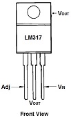
The best and most effective testing technique to test this IC is out of the PCB. For the pin out of this IC please refer to the exactly IC datasheet what you have to test. In this document, I will use the LM317T regulator and the pin out is usually the same with other LM317 family.
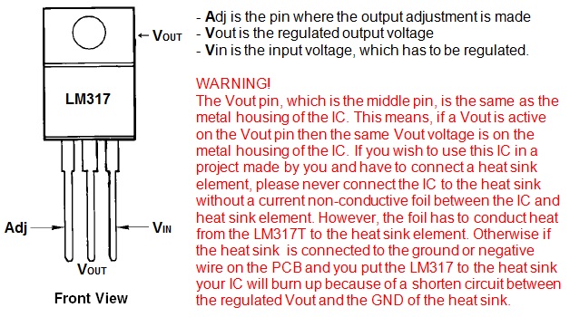
Here is the pin out of the LM317T:
Short circuit testing:
Take out from the PCB the LM317 and use your well used DMM to check for shorten pins between all the pins. No pins have to be in short. Otherwise, the IC is shorted and bad. Change the IC with new one with the same load performance.
Voltage regulation testing:
This is the most complicated part. Here is the adjustable resistor calculating formula how to calculate the relation between the adjust resistor and the Vout:
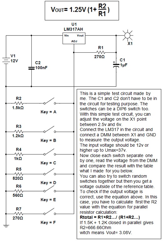
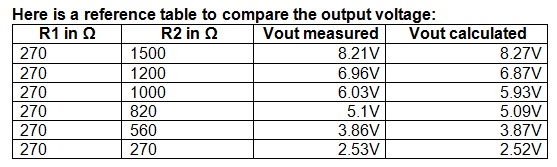
If you build the above simple circuit, you can test your LM317 easily. Close one desired switch, read the output voltage and compare with this table.
If you close on same time more then one switch then you have to manual calculate the R2 value with the parallel resistance equation first, and then use the above equation to calculate the output voltage and compare the result with the output voltage shown by your DMM. In your calculations and measurement you will get some small differences, this is because the tolerance of the resistors, the LM317 and the precision of the DMM. Don’t worry about that, that is normal and is around +-5%.
Somebody would say does putting a potentiometer in place of the R2 would be an easier way to adjust the voltage. Yes, that would be but then I suggest to put in series another resistor around 100 Ohm or so with the potentiometer. This is because in some datasheet, they take attention not to short out the Adj pin and that will happen if you put the potmeter in 0 Ohm position. The I-Adj can rise over the Iadj_max and can kill the IC.
WARNING!
Never use the test circuit for in-circuit testing purpose. The input voltage of the tester could damage some components on the PCB. Whenever you test the LM317, take it out from the PCB and connect it to the test circuit.
I hope you enjoy this tutorial and will save lot of repair time.

This article was prepared for you by Christian Robert Adzic from Novi Knezevac-Serbia.
Please give a support by clicking on the social buttons below. Your feedback on the post is welcome. Please leave it in the comments.
P.S- If you enjoyed reading this, click here to subscribe to my blog (free subscription). That way, you’ll never miss a post. You can also forward this website link to your friends and colleagues-thanks!
Note: You can check his previous post in the below link:
https://www.jestineyong.com/pc-intel-d-326-cooling-problem-solved/
 (176)Dislikes
 (0)
(0)
36 Comments
Leave a Reply


Ulises Aguilar Pazzani
October 21, 2015 at 8:48 am
it looks like a good projets , I will look in to it
Robert Calk
October 21, 2015 at 9:33 am
Nice job, Chris. But I don't know why the guy wanted you to write an article instead of just going to the datasheet? There are all kinds of schematics and information on the IC in the datasheet.
Albert van Bemmelen
October 21, 2015 at 4:50 pm
I agree Robert. Although there are many readers who don't even know what a Datasheet is. And Chris in that case did a nice job here. But I have to agree that when people ask me questions like were to put the Test Light Bulb, they've lost my interest!
Paris Azis
October 21, 2015 at 6:12 pm
Hello Albert
You should not get upset with such questions (and this refers to Robert as well) since it is more than obvious that they are put by beginners...
Let's encourage them (in a safe way for themselves of course) instead of losing our patience with them.
Schools (if any on the subject any longer) do not teach tricks like the lamp test. These are all derivatives of accumulated experience of old technicians and this exactly what is needed to be a legacy to the new generation of repairs experts. Otherwise they will get disappointed and quit their attempts on the subject (I humbly think)...
Best Regards to both of you!
Albert van Bemmelen
October 21, 2015 at 10:29 pm
Thanks Chris. As long as you don't make such difficult articles about hacking devices with Eeproms, I won't ask you those nerving stupid questions (LOL). But I can't wait on any new items you are able to share with us regarding this knowledge.
Albert van Bemmelen
October 22, 2015 at 4:09 am
Hi Paris, I understand what you mean and of course you are right. But I do hope to learn from others on Jestine's Blog. It is for instance a shame no one of you Guys is familiar with programming FPGA's and CPLD's in VHDL.
I know a bit or two about the VHDL code but I somehow can't get the old ModelSim or other Simulators running. I only have the very difficult Free Xilinx, and the 2 year free Atmel EDA software running without the ModelSim (is removed from the packages) Simulator. But luckily the limited Free Simili symphony eda sonata 3.1 works nicely. It would sure be nice to hear from more experienced programmers on this Blog. Because VHDL is really great and not at all difficult to learn just like Basic ! And the best part is that it is not a sequential programming language but a parallel running language code! Every bit of code on inputs or outputs, and in the VHDL programmed chip runs simultaneous. Unlike BASIC, C++ or any other old language!
Robert Calk
October 22, 2015 at 1:07 pm
Hi Albert,
I will probably start learning code before too long. I've played around with an Arduino a little bit, but I haven't got serious about it yet.
Albert van Bemmelen
October 22, 2015 at 3:02 pm
Me too Robert. I own more different Arduinos and I do like the free Arduino software environment. But somehow the Arduino programming language code isn't like C or C+ it only looks like it is, but uses its own kind of rules. And because in Arduino you can use boolean, and digital arithmic in one sentence together unlike the way you do in C, it makes it harder to comprehend. For instance a line like this one :
if (key_read(row1,row0,row2)==LOW) drives me crazy because it just doesn't exist in C. And hardly is understandably explained in Arduino.
But I did make a Floppy to SD card copier which works in Bascom and an Arduino Mega 2560 Board. Which I only had to translate from the Polish language to an English version because the original code was made by a great Polish Author (Thomasz Sadzikowski).
Chris
October 24, 2015 at 7:58 am
Hi to all here, I have experience to write code in C,Basic, ASM, Hex even in binary too. No mater is it an eeprom content or a firmware mod for a uC or just a file on the hdd.
I will say, for the very first time, it is very important to make a choice what will I do and then how.
For first I advice to enter into the AVR world but not with Arduino. That is a good product but if you wish the complete picture then use a regular development board like this on this link:
http://www.mikroe.com/avr/development-boards/
This is a complete development environment.
Then make a choice which programming language to use.
No mater which programming language you are use from the 3 of them (C, ASM, Basic) if you are on the beginning.
I prefer C or Basic. ASM is a bit harder ad maybe more complex then the other two. ASM runs faster in the uC but in real I never done some intergalactic time travelling vehicle with this uC and I don't need some extra speedy software in the uC.
For diy project C or Basic is more than enough.
The AVR family is large and meet all of our need.
Of course you can use PIC too, no problem.
Just start with one of these two uC, let the other uC's for some other time.
I use the AVR uC in car electronic and some diy project's now days.
YOu can make a car diag tool with an AVR uC. Is that not enough?
Just start digging with the right dev. board and make some cool thinks with it...
Albert van Bemmelen
October 26, 2015 at 3:41 am
Thanks Chris. I understand what you wrote. I do have a degree in Basic, and know a bit about Assembly, and Java, and how to program in Flowcode, Bascom and stuff.
But all these programming languages are for micro-processors/micro-controllers. And are just 'old' sequential languages.
VHDL (also called HDL, or the Verilog version) is brandnew
(made by the USA Defence in de 80's) and is a parallelprogramming language.
In which you are able to write complex Digital Electronic Circuits, even micro-controllers! By using simple text commands (in VHDL or Verilog), and afterwards you program this code into FPGAs / CPLDs that are fast flashable.
And after this they work very fast stand-alone
(easily around 200MHz or faster !)
and can contain a complete computer board with thousands of components in a little Complex Logic IC. And the FPGA/CPLD holds its program (the retention time), or the complete digital circuit if you like, without the need of Backup Batteries for decades. Probably most new Computer boards now do contain a few of these complex chips. And the Development programs for this VHDL/Verilog language, include Simulators and Schematic Designing, are very high priced.
And also require more time to learn how to use them. But this is really interesting for Electronic Engineers because of the possibilities and the Fast results. Also making a new redesign after any mistake is much easier then it used to be when you had a complete board with lots of components.
Chris
October 26, 2015 at 5:39 pm
I absolutely agree with you, but that is a bit higher thematic for the most electronic hobbyist's and repair technicians. Even the world of uC's are for lot of the technicians unknown too...
I don't know, I think on this blog are people who repair now days electronic tools and equipment and the thematic about we ( two of as ) talking about is a bit complex for this blog users.
Maybe someone of as should start to write some articles about of the FPGA etc. and we will see the reaction.
Give you a try if you have time.
Albert van Bemmelen
October 28, 2015 at 4:48 am
Thanks Chris, I guess you are a lot quicker in starting in VHDL or Verilog if you are interested (Verilog code is very short and beautiful but therefore harder to learn I think). I so far have invested in buying a lot of different FPGA/VHDL programmers already, and I've printed out a lot of books on the matter VHDL. And also Ebooks on the subject. But sadly the Free Software (like Xilinx's Webversion) is very complex and the schematics not as nice, and the easier versions from other Developers are in contrast much better looking schematic wise but just to expensive. And this does making a start in VHDL much more complex it needn't have to be. And only students at a University get most software as a special deal for free or in a beginners version.
Albert van Bemmelen
October 21, 2015 at 8:05 pm
PS: I remembered that you also can build a very crafty AM Transmitter with those LM317's. See for instance: http://www.qsl.net/qrp/tx/317-tx.htm
And I also have seen circuits with a couple or 8 or so in them for making a Regulated 10 A Power Supplies. (1.5A per LM317).
Gerald
October 23, 2015 at 11:38 am
This is cool Albert, thanks for the link. As a former radio ham I love to read about those types of creative circuits.
Cheers,
GM
Albert van Bemmelen
October 26, 2015 at 4:06 am
Thanks Gerald. I like those little projects very much too. I also saw another simple AM transmitter somewhere that only used a 4 pole Quartz oscillator and a few passive components around it. So there are more ways to build one. Sadly AM gets lesser and lesser attention, and it seems that the AM Band hardly has left any 'quality' Radiostations left. Maybe it will become a free Radio-Amateur Band in the near future. Who nows? I also saw a FM transmitter project that simply used a Raspberry Pi as programmable Transmitter.
Humberto
October 21, 2015 at 9:35 pm
First of all the project of Chris is correct, and useful too. But Albert I agree with you too, in my country there are many techs who are autodidacts, and never studied the Electronics Science at the school or even at the University, therefore they can't use the datasheets of an electronic component at all.
Albert van Bemmelen
October 21, 2015 at 10:51 pm
Yes Humberto. Easy repairs are easy money, but often not very interesting. Since the Basics will always be the same. And the better we understand the Basics, the better we are able to solve the more complex repairs. Whereas only the complex repairs will expand our knowledge in Electronics. Knowledge is like a staircase: we won't get to the top if we do not start at the bottom.
Gerald
October 21, 2015 at 9:38 am
Hi Christian,
Excellent tutorial with great illustrations. One point I was wondering if it would be good to put a small load to your test circuit in order to simulate a bit more the real conditions. Something like a 150 Ohm resistor that would draw around 50 mA at the highest voltage (8.27 V). What do you think?
Cheers,
Gerald
Chris
October 22, 2015 at 3:13 am
Hi Gerald, thank you for supporting my article.
The idea to put under load the LM317 is a good ide, but, if you wish to load the LM317T witch has a Iout_max 1.5A with 50mA this is in reality not a testing load for this IC. When you try to load the LM317L witch has Iout_max is 100mA then it would be ok as a test load.
Never mind, in most of case, if the IC is bad you have no Vout or the Vout is incorrect or with some noise in the output voltage.
Of course it is not a bad idea to put a test load to the output if you are not too lazy for that, but the load should be in a relation of what is the Iout_max of the IC under the testing condition.
Gerald
October 22, 2015 at 8:23 pm
Hi Christian,
I got your point. My idea was that we need a certain amount of load when we test a voltage source. For example if you put your DMM across a worn out 9 V battery you might measure 9 V or more. As soon you connect some load, the voltage might go down to 8 or 6 or even less volts. You don’t need the maximum load to see that the battery is bad.
The idea with the LM317 is the same. I don’t have any experience about this chip; I just assumed that if it can supply 50 mA without its voltage dropping it would be OK. I Might be wrong. In such case, please go ahead and go for 1A or 1.5 A. By no mean this will be a better test. I am still a believer that a voltage source must be tested under some kind of load.
Cheers,
GM
Chris
November 2, 2015 at 11:02 pm
Gerald I'm agree with you of course. Your idea of testing is absolutely in place.
Thank you for your comment.
rauljose go
October 21, 2015 at 10:13 am
hello Chris, good info for this article, nice and i believe this would help us for the repair jobs. many thanks again.
marcos aurelio
October 21, 2015 at 11:30 am
very good.
sagar sen
October 21, 2015 at 11:59 am
sir,you save my 317 ic's because i lost more then 15 317 ic... Thank u..
Chris
October 22, 2015 at 2:21 am
You are well come mate. 🙂
Thank you for supporting my articles...
Zed Pato
October 21, 2015 at 1:10 pm
nice information sir regarding testing lm317 using your circuit. can i follow up sir Christian about your esr meter that has capability to measure up to 200 ohms can you share it sir here the diagram. Thank you so much
Yogesh Panchal
October 21, 2015 at 2:08 pm
Chris,
Thanks for sharing idea.
Paris Azis
October 21, 2015 at 6:25 pm
Hello Chris
Although your article is beyond the interest of any experienced technician, I believe that it will help the inexperience ones.
Especially if they think (after reading your article) that in such cases the best test circuit is the circuit under repair and that if the two resistors (R1 and R2) of the shown above simple mathematical formula are intact in the circuit they have under repair, then the LM 317 HAS TO give the output this formula predicts, OR ELSE IT’S DEFECTIVE.
Anyway you did good job with it.
Best Regards
Chris
October 22, 2015 at 2:19 am
Azis, thank you for supporting my articles.
I give a like to your comment, I agree with you does the best test circuit is the circuit under repair. But this is only for technicians novices or so, for who it is confused a bit how is wired up the LM317 in his own circuit. I think we who are day by day in the world of electronic projects or in repairing stuff for as it is easy to do the job, but for an entry leveler this would be maybe educative.
I don't know, the article is still here and I hope for someone will be helpfully ...
My best regards.
Corriete
October 21, 2015 at 6:59 pm
thanks you for supporting the electronics world. a the best in the future..
Andre Gopee
October 21, 2015 at 9:33 pm
Hi Chris,nice article. this a good project.
Henrique Jorge Guimarães Ulbrich - Brazil
October 22, 2015 at 4:18 am
Very good, Chris. Just a comment: in the beginning, when you describe the IC, perhaps the sentence "Vin is the input voltage, which has to be regulated" would be better "Vin is the input voltage, which has NOT to be regulated"
mahmoud
October 22, 2015 at 5:31 am
Hi dear Christian this article is very useful for me thank u very very much.
reza
October 24, 2015 at 4:52 am
hi Christian
thank u
Vicken Mardiros
November 7, 2015 at 3:17 pm
thanks Christian it was so helpful for my student this test LM 317
Ulises Aguilar
April 4, 2020 at 2:30 pm
Mr Knezevac thk´s for the information , i will get to it right away