
Miracle Restoration Of A Prestigous Normende Tube (Valve) Radio


I am so excited to write this article because of a miraculous result that enabled restoration of this wonderful antique Radio, after several futile efforts put in for weeks together! This Radio was brought by my schoolmate stating that it was picked up just for its fancy look during his visit to a faraway place. The set was getting on and was connected with an external FM board and it produced only a feeble sound, though all the valves glowed. He asked me to try my best to restore it as it was a many sought after set belonging to the yesteryears. Though there are 210 snaps taken at various stages of the work, I am including only a few relevant for this very brief report of the work.
On opening the back cover, I could see a lot of dust settled inside, broken and fallen off AM Rod antenna, with its coil pulled out, a defective capacitor fallen off from somewhere, two speakers were missing out of the four, coils were tampered and some wires were hanging etc. The list may run to over a page! After dismantling the chassis from the cabinet, I subjected it to a thorough cleaning to the extent possible. The service manual was not available and my best efforts to get one through various antique forums globally did not yield a result. The model number sticker was torn and I could not provide this number when some suppliers asked for it. But I did download available Nordmende Tube Radio circuits and referred to circuits that looked similar. The Radio Museum had this entry, which might be of interest to the readers too:
https://www.radiomuseum.org/r/nordmende_9150.html
Though the output valve numbers were seen as ELL80 in the above entry, this had EL84s with ECC82s. Rest of the valves were same.
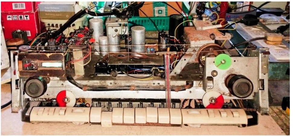
To tell you frankly, I was flabbergasted by looking at the complex circuitry and was wondering whether I asked for trouble! There was some itching to give up too, which I somehow managed to suppress. Here, have a look at the rear and decide yourselves:

As usual, my first attempt was to restore the Amplifier section, for which checking of voltages present at various pins were important. Those of you, who are interested to study the schematics of Nordmende radios, can visit the following link:
https://www.rsp-italy.it/Electronics/Radio%20Schematics/Nordmende/index.htm
This is from where I downloaded all the Tube Radio Schematics. But they are in German Language and some portions are unreadable too. But we only need the connections and it will help us to that extent.
First advice in many antique Radio refurbishing websites is to replace all the capacitors (both electrolytic and fixed) as these would certainly have deteriorated due to ageing. Just look at a couple of readings that I am sharing to prove that:

The value written on the first cap was 0.1uF and the second one was 100pF. 100nF was reading 618.6nF and 100pF was reading 1960pF. Now you can judge their advice yourselves!
I had to pull out the Volume Control with its fittings to replace such caps on it, after removing the glass dial and connected fittings.

In the process, I saw a few resistors also with values increased, some almost double, in the Amplifier and Pre-amplifier section. I dismantled the fixtures of Bass/Treble switch assemblies and carried out replacement of caps in it too. After doing this time consuming complex work, I applied power and checked the voltages at pins of valves and found these to be normal. Therefore, gave an external audio input, using my testing speakers, the output was superb!
Having revived the Amplifier section, I turned my attention to the Radio Side. First of all I replaced all the capacitors in the circuitry including the caps inside the IFTs. Styroflex capacitors were provided from my following collection, accuracy of which was checked before replacement:

The IFTs, fortunately, showed continuity and responded to tuning to 455Khz signal input. But it was not picking up any of the stations in any band. Forgot to mention that I fixed the Rod AM Antenna in its place and continuity was also checked. The voltages of EBF89 and ECH81 were ok. Since the voltage was varying in the grid in ECH81 valve, while tuning, the oscillation was taking place. But no RF signals reached the stage for process. The RF amplifier Valve ECC85 was suspected to be defective as the output was not coming from it. A replacement valve was not available even in the market. I tried bypassing it, but still there was no pick up. This was clearly a result of spoilage of the RF section, which contained the RF coils and gang Condenser. I removed the dust cap of the gang condenser and noticed that it was very clean and neat. No dust or dirt was present and the leaves were neat and clean too. I checked the capacitance connecting a meter and turning the spindle. It varied smoothly. There were three gangs in the unit. While tracking the wiring, I could see that two were for the MW/SW band up to 4 and yet another one was getting connected to bands 5 & 6. Feeling very vexed, I dismantled the band switch to study the connections and to look for any short or open circuits.

After trying by connecting each set of oscillator/corresponding antenna coils you find in the above pictures, separately, with negative results, I decided it was time to take a drastic decision. I looked through my antique RF coil collections and found two Medium Wave Antenna Coils of different companies, but Oscillator coil was missing. Then I had Short Wave 1 & 2 full set. So, I assembled them together on a board for testing connecting it to the ECH81 valve inputs.

For testing purpose, I ignored the MW section and tried only the Short Waves. But even then no pick of stations. Well, after reading my previous notes and articles on various Valve Radio services, looking through and studying comments of various people around the world in the Antique Radio forums, I concluded that the IFTs were not matching the coils that I have tried. This Radio had three IFTs. Two in the Mixer stage and one in the inter stage. The output from the Mixer stage IFT was fed to another IFT for interface with EBF89 valve. I removed the IFTs to study the connections:

The connections of these two IFTs, i.e, Mixer and input IFTs, were different. That’s how I decided to replace them and provide an IFT made out of transistor Radio IFTs. I followed the circuits given below for constructing the IFT:
http://www.angelfire.com/electronic/funwithtubes/IF_Can-1.html
Here is the end result:

Fixed it in place and modified the ECH81 valve connections as per the following diagram up to the input to EBF89 Valve, replacing the resistors and capacitors to match the diagram and wiring the new IFT.
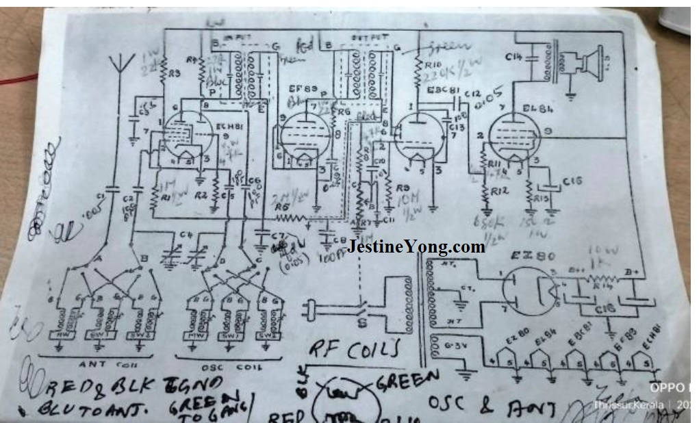
As for the MW, I experimented by using one Antenna coil as RF Coil and another as Antenna Coil. Now how to check which pin has to go to ground and which one has to be connected as inputs to ECH81 Valve? This was done by trial and error and from experience. Any wrong connection in the Oscillator Section would give a howl. Any wrong connection in the Antenna Connection would give a dead result. Small Coil is always the input for mixing and larger coil is for oscillation. You can see how these are given as inputs to ECH81 valve very clearly in the schematic given above. The Antenna input is fed to small coil of the Ant Coil, secondary of which is fed to Pin 2 and Gang. Another pin of Gang joined to Oscillator Coil Primary is connected to pin 8 and Secondary is fed to Pin 7/9. Thus the input is matched and balanced with the oscillation with the help of Gang when we tune the stations. Simultaneously it is mixed and amplified by the Valve and fed to input of the next IFT. There were several trial and errors including re-tuning the IFTs individually and collectively. Then the miracle happened! I had provided a padder (a large size trimmer), which is a variable small capacitor for fine tuning the RF section for peak output and positioning. (More details can be had from https://www.antiqradio.com/post_padder-feedback.html ) The MW started working very well! It was so good that between stations there were absolute silence! This indeed was a miracle! How could an Antenna Coil work as oscillator that too with perfect matching! Nothing but miracle and luck of the customer. I tried the SW1 and SW2 and these also worked very well.
So, I stripped all the coils from the band switch and fixed the coils I had with the original trimmers in appropriate places and wired it so that MW, SW1 and SW2 band switches could be used for its selection. Following are pictures of completely stripped Band switch, and starting of placement and wiring of the coils that I had.

Replaced the dial cord and adjusted it to proper position, connected the speakers and closed the cabinet and called the customer to come and see. He was amazed to see the results and really thanked me from the bottom of his heart! I tried it for a few days before giving delivery!

Mission accomplished with the support of miracles and luck and satisfaction therefore got multiplied and bag had to readjust like a python to accommodate it! (LOL)


This article was prepared for you by Parasuraman Subramanian from India. He is 74 years old and has more than 30 years’ experience in handling antique equipment like Valve Radio, Amps, Reel Tape Recorders and currently studying latest tech-classes conducted by Kerala State Electronics Technicians’ Association. He has done graduation in BBA degree, private diploma in Radio Engineering and retired as MD of a USA company. Presently working as Consultant to Hospital and other institutions.
Please give a support by clicking on the social buttons below. Your feedback on the post is welcome. Please leave it in the comments.
P.S-If you enjoyed reading this, click here to subscribe to my blog (free subscription). That way, you’ll never miss a post. You can also forward this website link to your friends and colleagues-thanks!
You may check on his previous article on Revisit Of HCT TV Monitor Model HLD-150MDP After A Gap Of Two Years
 (47)Dislikes
 (0)
(0)
18 Comments
Leave a Reply


Anton
January 27, 2024 at 5:56 pm
Amazing restoration work!
Parasuraman S
January 27, 2024 at 9:44 pm
Many thanks, dear!
Ajay Kumar
January 27, 2024 at 8:10 pm
Wow, that was a very detailed explanation Sir, and it is wonderful to note that your persistence and effort paid off well. I would love to visit and observe how you put in such painstaking efforts to set right the radios, especially the valve sets. Am from Pondicherry and visit Kerala once in a rare while. Thank you for the explanations and pictures
Parasuraman S
January 27, 2024 at 9:46 pm
You are welcome! Many thanks for your loving comments and encouragement!
Lawrence Pina
January 27, 2024 at 11:45 pm
I continue to be amazed by your skill, patience and persistence. What a great example you set. Have you considered starting a Parasuraman Subramanian Electronics Repair channel on YouTube? You can influence many more people there and make good money at it too. I don't have 1/2 the skill you have and my channel's been quite successful. Please consider...
Parasuraman S
January 28, 2024 at 9:17 pm
Many thanks for your wonderful comments and suggestions. I think Jestine Yong's blog itself is doing a good job of sharing skills around the world and I don't find a need for another channel to showcase my skills alone. I would love to continue here in this way. Neither do I have the facility to take good quality videos nor am I interested in making such videos! Nevertheless I do appreciate your concern and sincerety in this advice!
DAVID PENTIN
January 28, 2024 at 12:07 am
It is good to see old valve radios being restored as they are usuaily built far better than the plastic rubbish which manufactures sell these days. Well done Sir!
Parasuraman S
January 28, 2024 at 1:06 pm
Many thanks for your comments. You are right about the plastic rubbish!
Yogesh Panchal
January 28, 2024 at 12:22 am
Sir,
I can't find the words to express.....Excellent!!
Never seen IFTs like these.....what type of capacitors you replaced with Styroflex capacitors?
Parasuraman S
January 28, 2024 at 1:07 pm
The values are different at stages. I try to use same type of caps wherever I can. Many thanks for your comments, dear!
Waleed Rishmawi
January 28, 2024 at 1:16 am
I am glad you did not give up. From looking at the photos you provided I can see and feel the stress you were under, I would have felt the same way. Thank for sharing your big success, I was encouraged by it and I am sure you enjoyed replacing all these capacitors.. LOL. Have a blessed day
Parasuraman S
January 28, 2024 at 1:09 pm
Yes, dear! Replacing the caps is as amusing as it was when I started it many years back. Its some sort of itching which I cannot resist! (LOL) Many thanks for your comments, dear friend!
Albert van Bemmelen
January 28, 2024 at 3:49 am
This article with the 210 snaps you took to preserve all findings could make a complete book on restoring this Nordmende tube valve radio!
Here was no doubt again a extremely experienced technician at work! Although it for me still would not make much sense if I had to do such a tedious task with so many setbacks myself. Valve tubes were never my thing although they make great powerful transmitter end-stages, although we now can use power-Fets instead.
Parasuraman S
January 28, 2024 at 1:10 pm
Well, a good suggestion! Many thanks for your expert comments and observations, dear! It is the passion that drives us all to go to this extent!
Robert Samuel
January 28, 2024 at 4:41 pm
Dear Sir,
Your patience and determination to fix even very badly damaged is praiseworthy.
I do follow your many repair and restoration jobs and remain amazed by your work.
Thank you for your postings.
Robert
Parasuraman S
January 28, 2024 at 9:19 pm
Your comments and encouragements are fuels for my forward propulsion! Many thanks!
Henrique J. G. Ulbrich
January 31, 2024 at 10:30 pm
All resumed in just one word, Parasuraman: AMAZING.
Parasuraman S
February 1, 2024 at 10:34 am
Many thanks for this amazing appreciation!