
Op-Amp IC Circuit Tester

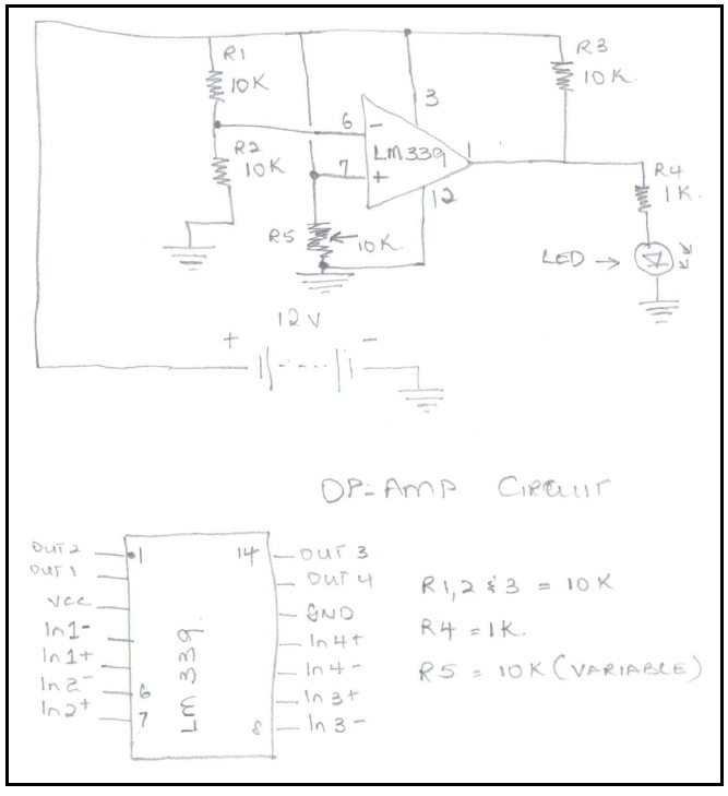
In the diagram above I am using an IC No. LM339 Op-Amp for my demonstration… You can use any op-amp for the tester just the input and output pins will be different.
· The supply is a 12Volts DC and supplies Pin 3 (Vcc) positive and Pin 12 (Gnd) negative.
· R1 and R2 are 10k which is a Voltage divider, between them would give you 6 volts to pin6 (input 2 Negative).
· R5 is a 10k Pot that goes to pin 7 (Input 2 Positive) and to ground.
· R3 is also a 10k resistor from the positive of the supply to pin 1 (Output 2).
· R4 is from Pin 1 to an LED.
You can connect the same for all inputs and outputs of the IC to Test.
Principle of operation
With a supply of 12 Volts DC to Pin 3 and which also passes through R1 and R2 to ground, between R1 & R2 you will get 6 Volts in reference to Ground that is going to pin6 (Input 2 Negative) which is a Constant voltage. However, on Pin 7 of LM339 a 10 K pot is supplying Voltage to the positive of input 2 and this can be varied from 0 to 12 volts DC using the POT. Theory is that if Pin 6 is 6 volts and by varying the 10K POT on Pin 7 to get above 6 Volts you will get an output on Pin 1 and the LED will be Lit, if the voltage on Pin 7 is lower that Pin 6 Volts Out 2 will be Zero. This Test can be done on all the inputs and outputs for the Op-Amp.
Note:
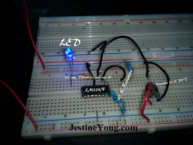
I built this tester on a Bread board with removable wires so I can adjust the inputs and outputs and power supply and you can test any op-amps that is 14, 16 pins etc. You really can’t make it a permanent fix because you will be changing around the wires for different op-amps. Different op-amps have different pins for power, input and outputs. Those who understand how the op-amp works will be able to easily test variety of Op amp ics. See the below picture of the circuit using a LM224N Chip.
This article was prepared for you by Andre Gopee from Calitech Limited Trinidad West Indies.
Please give a support by clicking on the social buttons below. Your feedback on the post is welcome. Please leave it in the comments.
By the way if you have any good repair article that you want me to publish in this blog please do contact me HERE.
 (145)Dislikes
 (9)
(9)
24 Comments
Leave a Reply
Cancel reply


Jackie Martley
October 30, 2014 at 9:02 pm
Good-morning, I always enjoy reading your articles. I think there is a typo in Op Amp Tester schematic. Pin 7 is directly connected to B+ so changing pot value will not change voltage on pin 7 of IC like you want it to. There should also be a current limit resistor inserted in the circuit so pot can swing to extreme limits and not burn up.
Let me know if I am incorrect.
But Thanks for the Great Idea because I understand your theory on how/why it works.
Thank You!
Jackie
Robert
October 31, 2014 at 4:57 am
From what I've learned the + input is the non-inverting input as you said. I believe that you are correct about the current limiting resistor for the pot as well.
Andre Gopee
November 1, 2014 at 1:16 am
Hi Jackie, There is no need for current limiting resistor as the center pin of the pot is connected to pin 7 and other connected to B+ and other to B-. So by varying the pot it will increase the voltage or decrease.
Yogesh Panchal
October 30, 2014 at 9:24 pm
informative article thanks for sharing.
Andre Gopee
November 1, 2014 at 1:16 am
Your welcome
Jayant Gholba
October 30, 2014 at 9:44 pm
Center point of pot should go to Pin 7 of IC. One of the fixed points of pot will go to B+ and the other to B- of supply. There is no need for current limiting resistor in series with pot.
Andre Gopee
November 1, 2014 at 1:18 am
exactly what I explain to Jackie. Thank you and your welcome.
Sethu ramachandran
October 30, 2014 at 10:34 pm
very good idea of testing Op amps , you have made people to understand the working of OP amps.
The actual connection in the Bread board and your schematic are not getting linked. can you correct the same.
Andre Gopee
November 1, 2014 at 1:21 am
Hi Sethu Thanks you... In the schematic I used an LM339 and In the picture I use a LM224 IC, so pin connection are different. In LM339 pin 3 is power and Lm224 pin 4 is power. Hope this clear it up for you.
beh
October 30, 2014 at 10:45 pm
HI Mr Gopee
thanks for all your efforts to find a way to test the OP-AMP ic s but this need 2 item :
1- you will need exact diagram of each ic
each ic has own pin lay out
2-you have to arrange the wires according the need of the special ic
i personally prefer to replace the suspect ic with good one and see what will happen in my recent article i used LM324N and/or DBL324 they are very cheap 10cent each in this country
Andre Gopee
November 1, 2014 at 2:01 am
Hi beh yes you need diagram for pin layout... but this diagram is just to explain how the IC works so you can check it directly on the board and see what input and outputs you get. Ic in my country are quite expensive as lm339 can go for 14 to 18 bucks here. so it is beneficial to test it before I wast good money.
Eugenijus Skardzius
October 30, 2014 at 10:57 pm
LM339 is a comparator , not opamp !
Andre Gopee
November 1, 2014 at 1:22 am
it is basically the same thing. Thank you.
Humberto
October 31, 2014 at 12:11 am
Good article, very informative. Thanks and keep up
Andre Gopee
November 1, 2014 at 2:02 am
Thanks Humberto
Mark
October 31, 2014 at 4:20 am
Hey Andre,
I enjoyed your article. I often wonder how to test IC's, so this was a good lesson.
Can you confirm the correct wiring as there seems to be quite a varied opinion about the connections. I would like to try this design to become more familiar with its use.
Andre Gopee
November 1, 2014 at 1:28 am
Hi Mark thank you... As I mention in my schematic i use an LM339 which pin 3 is Vcc, 12 is Ground, 6 is input 2- and pin7 is input2_ with pin1 as out put2. In the picture pin 4 is Vcc and pin 11 is ground, If you pull up the Data sheet for both IC you will see what I am talking about.
Robert
October 31, 2014 at 5:01 am
Thanks Andre. I just check the voltages while the op-amp is in the device.
Andre Gopee
November 1, 2014 at 1:29 am
Thanks Robert.
mahmoud
October 31, 2014 at 5:28 am
hi Andre thanks a lot this tester very useful especial for me.hope you are successful to research electronic.
yektaj
October 31, 2014 at 9:32 am
With the best regards to Dear Yong
In elektor magazine there is a circuit op amp tester with pcb.What for one op amp IC,2 op amp &4 opamp as LM324 with pcb .
Thanks
César Rodríguez.P.
October 31, 2014 at 3:34 pm
According to the scheme of the header on this page, the non-inverting pin is provided to the non-inverting and VCC to VCC / 2 at the output of the AOP is always at a high level and LED always on . The wiper of the potentiometer and should just go directly to the non-inverting pin so this way you can change the output status and test the AOP .
Greetings .
l.boopathiraj
November 2, 2014 at 9:48 pm
DEAR SIR
yes lot of op amp IC's available in the market here is some popular
IC's LM 741 this is common for all type of projects single op amp LM 358 dual op amp using sub woofer and LM 324 LM 339 contains like four op amps, ic s are different pin outs (refer only data) op amp IC's need dual power supply for best performance and normal power supply its ok
gcharal
November 4, 2014 at 12:01 am
Hello Andre,
thanks for this good article.
But I have a question.
What is the purpose of the R3 resistor?
Thanks again.
George