
PS3 Yellow Light Of Death Repaired

Ok. So I can hear a lot of you saying, “That’s not the best way to carry out a repair. It’ll never last!” And you know what? You are probably right! But, I got given this Play Station 3 for nothing regardless of whether I fixed it or not. So if it lasts for a while, then I have a few games and have had another excellent electronic repair experience.
So, let’s get down to the repair…..
My son-in-law gave me 2 PS3’s that both suffered from the dreaded YLOD (Yellow light Of Death) and it is a fairly common problem, especially with the older styles, known as the Fat Boy (er, coz it’s fatter than the later slim styles!)
As usual, I did some research using my best friend (sad I know) the internet! After some time I found an excellent article and video that walks you through the repair steps.
https://www.ifixit.com/Guide/Yellow+Light+of+Death+Repair/3654
However, I did find the steps provided were very basic, with no real specifics. I also found in the comments below, this method didn’t seem to last too long or damaged the board beyond repair. I figured that some of the people that attempted the repair perhaps didn’t have the skills needed.
The main problem with the YLOD with the PS3 (gotta love acronyms!) is that with the many hours of gaming done by the user and accumulation of dust around the fan and other components, a lack of cooling allows the solder on the CPU (Central Processing Unit) and the GPU (Graphics Processing Unit) becomes brittle and cracks, creating cold solder joints and therefore the unit will not operate.
So I decided to do some extra research on reflowing circuit boards. As I didn’t have a reflow station, I figured that I would just use what I had and see how things turned out.
By using the method shown in the picture here, I was able to use a combination of a kitchen oven (while my wife wasn’t home – of course), an air heat gun and an infrared thermometer.
So let’s start at the beginning.
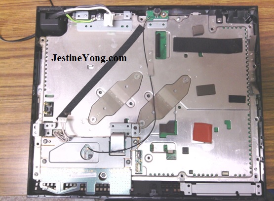
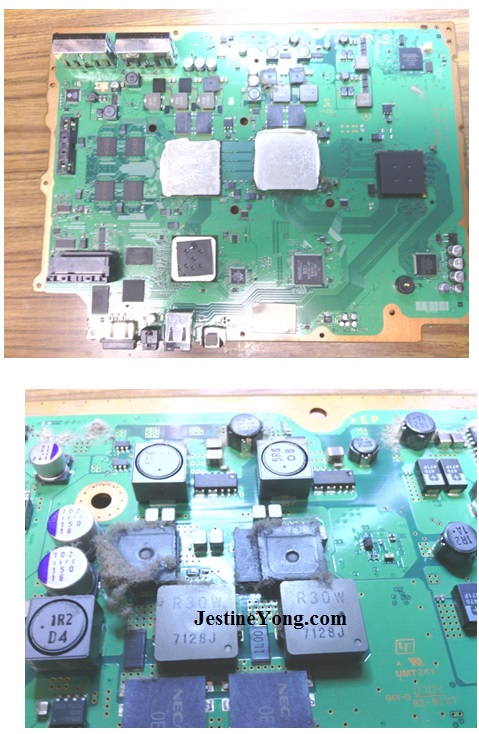
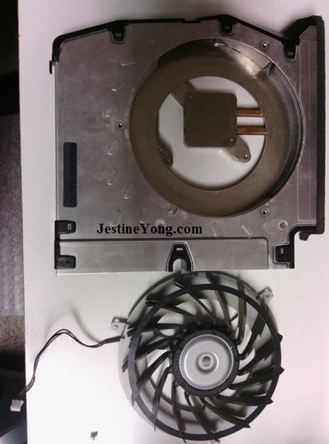
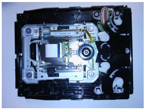
By following the disassembly instructions, I was easily able to get the mainboard from the unit. As I did so, I could see why the unit had failed – dust was everywhere and in the time my son-in-law had used it, it had certainly had a good workout!
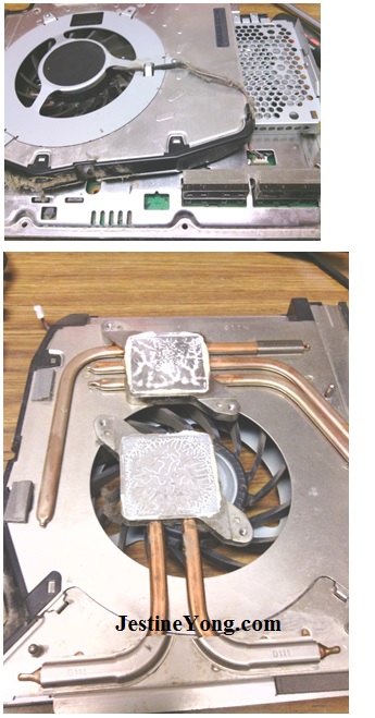
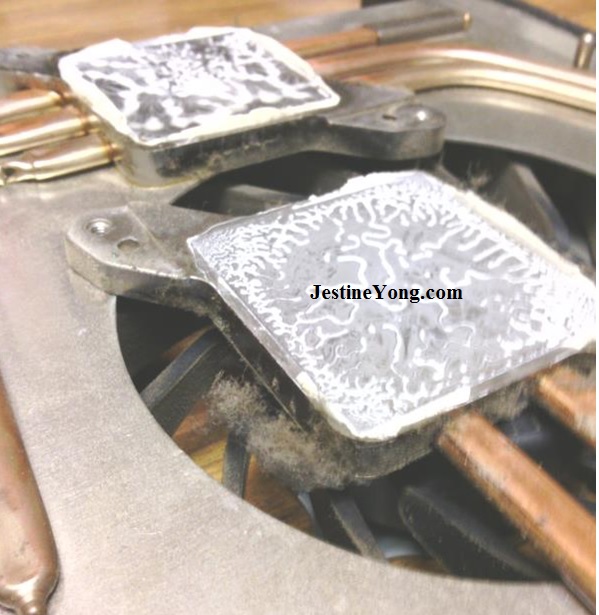
The fan showed clear signs of lack of cooling and airflow. The two metal pads shown here sit directly on the CPU and GPU, allowing heat transfer.
After removing the mainboard, I was ready for the next step. I had never done a repair like this before, so I was a little apprehensive. It sat in my lab for a few months before I gained confidence to tackle it.
Even the mainboard shows how much dust had accumulated over the years.
It was necessary to remove all the thermal pads and thermal paste before applying any heat. According to the instructions, you should just preheat the board with a heat gun. I felt that would not provide consistent heat coverage and could increase the rate of failure. So, that’s where the oven comes in.
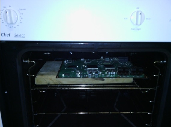
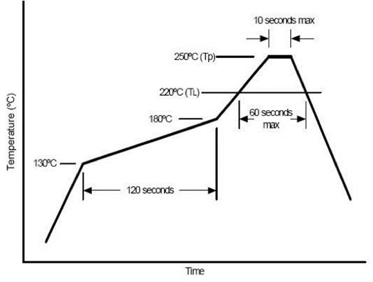
After carefully reading the reflow chart at the beginning of the article and organising all my tools and equipment, then turned on the oven to get that ready. Timing is everything! Too much and you end up with a circuit board in a puddle of solder. Too little and you have spent several hours doing absolutely nothing!
I had a stop watch on standby. I placed the circuit board in the oven at 130°C on a bread board to keep it level. I checked the board regularly with the thermometer to see when it was ‘done’.
Next it was into the lab with the heat gun, stop watch and thermometer. Once again I followed the chart above carefully, just adding a few seconds to allow for ambient temperature.
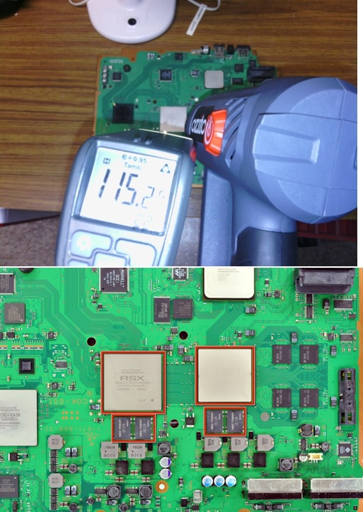
Starting with the CPU and GPU, heating should be done in a zig zag or circular motion to stop localised heat. After the correct time has passed, move on to the smaller chips below, using the same method. Remember, the solder will be in a liquid state, so any movement of the board at this stage could be disastrous! After the correct heating method correctly timed, the next step is critical – walk away and don’t touch it. Remember that you have reflowed the solder and have to allow time for it to harden properly. I decided to be on the safe side and let it sit overnight. Then it was just a matter of getting it back together in the reverse order – right?
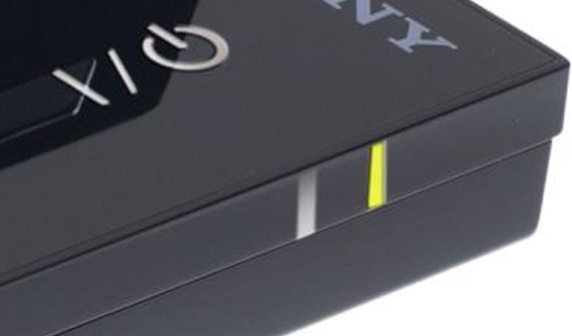
After reassembly, with my fingers and toes crossed, I pressed the standby button. No more YLOD and the light turned a solid green colour. I was on a winner and confidence was high! All I had to do now was put in a game and see how everything worked. I slowly pushed in the disc and found nothing happened. So naturally I started going through all the work I had done, thinking there was something I had missed! I decided to do further research…..
I found an article on misaligned Blu Ray players. In my case, this was a result of the PS3 shutting down before the Blu Ray had a chance to eject the disc correctly.
http://www.wikihow.com/Realign-Your-Ps3’s-Blu-Ray-So-That-a-Disc-Can-Load-and-Eject

This article was prepared for you by Mark Rabone from Australia.
Please give a support by clicking on the social buttons below. Your feedback on the post is welcome. Please leave it in the comments.
P.S- Do you know of any your friends who would benefit from this content that you are reading now? If so, forward this website to your friends or you can invite your friends to subscribe to my newsletter for free in this Link.
 (140)Dislikes
 (4)
(4)
35 Comments
Leave a Reply
Cancel reply


Robert Calk
August 1, 2015 at 5:56 pm
Good job, Mark. Thanks for the good links.
erra
August 1, 2015 at 6:19 pm
Hello Mark,
Many thanks for sharing this. I am impressed the way you tackled the problem. Please let us know how long this repair will last. I guess the rate of cooling is very important to avoid developing further cracks. I have heard that, for a long term solution, the chips need to be removed, getting rid of all solders from the chips and board, and re-solder them with new solders balls (typically 0.6 mm 0.45 BGA Rework Leaded Reballing Reflowing Solder Balls)
Mark
August 1, 2015 at 7:20 pm
Hey Erra,
Yes I agree. I have heard that this method is usually short term. However, I have stuck to the reflow temperature and timing fairly carefully and hopefully this will help. The method shown on the net is very vague and I'm sure many people have just waved a hot air gun around hoping for the best without any real knowledge of thermal transfer.
I don't usually play many video games. Perhaps I should lend it to a friend to see how long it lasts.
Thanks for your comments.
Albert
August 1, 2015 at 7:48 pm
You are doing the undoable at home without using the standard expensive BGA Hotfix equipment, Mark! But also by using the Hotfix curve that is used on those mostly pc controlled Hotfix machines. I also like to know how long it lasts because even on a expensive Hotfix machine there are no guarantees it will last forever. (In fact it may have to be repeated within a year if it didn't last).
I wouldn't use my Oven though out of health reasons.
I myself own a Xbox360 and do not need to Hotfix it in case of the Red Ring Of Death (RROD) occurs. All simply because there are very good repair sets available for the MS Console that not only repair the BGA error but also prevent it from happening again. Without any External Hotfix and by using a new Cooler Plate enhancement construction that corrects any unwanted mechanicle pressure on the Mainboard that could cause a new BGA CPU/GPU/DRAM Red Ring of Death Error. And also only by using the generated heath from the XBOX360 itself by turning off the FAN and after a minute or 10 (all in the manual from the Repair Kit Pro II) when you replaced and enhanced the Cooling construction, you simply switch on your FAN and XBOX 360. And probably don't have to fix it ever again for this RROD. (There are several versions on the Market and the original Repair Set II has about 100 replacement parts inside, like new DVD driver Belts etc. And only that set doesn't require any drilling in the Cooler Metal or the original XBOX Cabinet!). They say it works for about 99% of all RROD errors.
Mark
August 2, 2015 at 5:56 am
Hey Albert,
Thanks for your comment. Yes I was a little apprehensive about using the oven, but not even a smell was produced as I thought there would be. I only did it to preheat the entire board.
I would be interested in finding out more information about the repair kit and process you mentioned.
Can you direct me to a web site or link please?
As I mentioned in the article, I have a second one to repair and would be interested in trying another method just to compare results.
Albert
August 5, 2015 at 12:12 am
I gladly would Help you in repairing your Sony PS consoles. But I only have repaired the Microsoft Xbox consoles. And they have that upgrade/repair kit mentioned. But here is the link that sold over 150.000 Repair Kits: http://team-xecuter.com/forums/threads/87998-How-To-Install-The-Extreme-Repair-Kit
I guess there are also similar repair kits for the PS consoles but my experience with them is close to zero. (Although I do have the Service-manuals for the first 3 PS Consoles that helps repairing them also).
I hope you are able to find a repair site that handles all system consoles including the PS Consoles.
By-the-way: The little toaster oven that Robert mentions is used in a project from Elektor Magazine to solder SMD Boards pc controlled!
Robert Calk
August 2, 2015 at 11:50 am
I would not use the "food" oven either. He should get a little toaster oven or something.
Robert Calk
August 7, 2015 at 5:52 pm
You are right, Albert. I did the Xbox upgrade fix on my Xbox and my oldest sons Xbox, and they are working great. I seldom play games but my son plays games on his every week and his unit is still working great with no problems. I probably only play a couple of hours a month.
Albert van Bemmelen
August 8, 2015 at 3:14 pm
That original 100 parts repair and replacement kit from Team-Xecuter was not the Kit I could obtain, so I used another Simular but lesser parts Kit from Ebay that because of this also still needed a lot of Drilling. Because sadly Team-Xecuter Kits can't be bought with PayPal. And I don't want to buy an expensive Credit Card for this first too. These Simular Kits are okay but lack a lot of adhesive Cooling Blocks, and other replacement parts like Drive Belts etc.
Gary
August 1, 2015 at 11:43 pm
Yeah i started with this but now just reball stuff its not easy but its not that difficult either I have two Dell 630 laptops to do this weekend.
Reball stuff only cost me £50.
Albert
August 2, 2015 at 6:08 am
Very nice when somebody dislikes our articles, but not without them telling what is wrong with our sincere written contribution. That is a bit unfair I think!
Robert Calk
August 2, 2015 at 11:47 am
It proves that they are cowards. They dislike me all the time.
Albert
August 5, 2015 at 12:18 am
Robert I can't imagine someone would dislike you or the great articles you present always very neat and tidy. In fact thanks to you I now own a great Tektronics 2465A Oscilloscope that also is Calibrated the next 30 years or so. (your great working Battery replacement article).
So I express my gratitude for You writing the good stuff!
Cheers.
Robert Calk
August 5, 2015 at 7:31 pm
Hi Albert,
You are very welcome, my friend! It was my pleasure. Plus there are people ripping us off wanting $500 or more claiming the scope will need re-calibration when a new battery is installed.They probably change the battery the same way I did without calibrating anybodies scope unless it needed to be calibrated to start with. I'm just glad I could help someone else from being ripped off. I'm glad your scope is working out well for you.
Albert
August 7, 2015 at 5:35 am
Thanks Robert! Your Battery Replacement article worked really great! A very good Electronics hobbyfriend of mine now also bought a 2465A DV Tektronics Scope in France on Ebay for much less money I had paid for mine. He asked me if I was able to find a Service Manual for this special DV Tektronics Oscilloscope. But I take it that only the 2465A version is to be found on the Internet. He (Erik B.) may try to get in touch with you for this Manual finding question. Maybe via Jestine or his repair Blog. But if you read this you probably could just confirm if such special DV manual exists?
Thanks!
Albert
August 7, 2015 at 5:47 am
And Robert, You're quite right about the ripping off story on Calibrating Oscilloscopes. Even Calibrating my very old Philips 10MHz Memory Oscilloscope would cost me an awfull lot of money. But Still these Scopes probably won't need replacing any Lithium Backup Battery I know of.
So nothing can be lost by losing the Backup Ram Standby Voltage either.
And I read about Calibration Prices over $1600 Dollar for my (45 year old?) Philips, that is just ridiculous. If not insane!
Robert Calk
August 7, 2015 at 6:01 pm
I think I got the manuals from the Tektronix site. The guy I bought my scope from provided the links to me, but it's been a while.
Albert van Bemmelen
August 8, 2015 at 2:55 pm
Thanks Robert, I will tell my good Tektronics DV friend that he needs to look on the Tektronics site for any existing DV Service Manual.
Robert Calk
August 8, 2015 at 11:46 pm
I emailed the manuals to him.
Robert Calk
August 11, 2015 at 6:53 am
I've tried to email the manuals to him twice and it doesn't seem to be getting through for some reason.
Albert
August 11, 2015 at 2:57 pm
Oh I didn't know Robert. He didn't tell me. I will ask him today what happened.
Thanks for Your much appreciated Help!
Albert
August 13, 2015 at 3:38 am
I couldn't reach my friend four a couple of days until today. He mailed me just now that he was sending Tek 2465a manuals to you Robert. Don't know why. And I don't know if he recieved your manuals. Guess he is abusievely thinking that you needed his? (His English is not that great, his German is much better). Sorry for any inconvenience. I don't know what happened, got no clue at all. I only know that his Tek 2465a DV will arrive any day now. I explained the situation to him but I am a bit confused. It must be the way he is, always helping anyone?
Robert Calk
August 13, 2015 at 10:44 am
Hi Albert,
I already have the manuals, thanks.
Albert
August 15, 2015 at 3:18 pm
I know Robert. My Electronics friend Erik send me a totally wrong and confusing text message. But as I now understand he told me later that recieving your mail was not possible being 20MB or larger? And he didn't answer on my message on his answering machine either. So I hope he doesn't have any problems concerning his new bought Tektronics DV Scope.
Gerald
August 2, 2015 at 6:28 am
Hi Mark,
Interesting stuff, thanks for sharing. I have been looking at
DIY reflow soldering and there are plenty of stories on the net, just like this one: http://www.freetronics.com.au/pages/surface-mount-soldering-with-a-toaster-oven#.Vb1Gl_lshDw
I still find this a bit intimidating and haven't done anything about it yet. But maybe one day...
Cheers,
Gerald
Behzad Rasteen
August 2, 2015 at 12:34 pm
Mark: good experience and thanks for article.
beh
August 2, 2015 at 6:27 pm
Hi Mark
three questions:
1- how long you keep the mother board in the oven ?2- what is the brand of your heat gun ? 3- with what degree you blow the hot air to the board
thanks
beh
Mark
August 4, 2015 at 7:25 am
Hey Beh,
I understand everyone's comments and that is why I stated at the beginning of the article that is obviously not the best method to do reflow work, but I don't have the confidence to do reballing at this stage and so I tried the cheats way.
As for the oven, I had fans on everywhere and I was concerned with the possible toxins, but it was only used during the preheat stage and only used it until it reached the required 130C. I kept opening the door to check with the thermometer. I turned on the oven with the circuit board inside so that it could heat up slowly. Afterwards no smell was even noticed. We have had many meals since and suffered no ill effects (apart from a strange twitch that has just started - kidding!) I used my automotive Tradequip infrared thermometer that ranges from -50C to 500C.
The heat gun used was a cheap Ozito brand from the hardware shop, with 2 fan speeds and temperature ranges from 50C through to 600C.
As for the time factor, I just followed the method shown in the diagram at the start of the article. It includes both temperature and time.
By using both the hot air gun and thermometer, it was successful. As for how long, only time will tell.
Thanks for all your comments. All queries raised were valid.
Mark
August 4, 2015 at 7:43 am
Also I guess the photo with the 115C and the heat gun may be a little confusing. I actually did this after the repair for the photo. It was difficult to balance all the tools and camera at once. Don't worry, the heat gun was actually focused on something else at the time and not at the circuit board - trick photography! I didn't want to mess up the work I had done just for the sake of a photo!
Albert
August 5, 2015 at 12:44 am
Hi Mark, Just a remark to add on using the HotFix Graph when trying to repair. At my bosses Service Repair Workplace our PC controlled Hotfix Machine could go to about 235 degrees Celsius. But that is only used when a first Hotfix attempt didn't work and only in the top in the curve for a very short time. BUT when we tried Apple Probook boards a max temp of 170 degrees Celsius is enough because the special CPU/GPU with RAM on top simply 'left its base' in the liquid tin/solder. And that needs to be prevented at all costs. And we also use some Hydride Fluid we injected under the BGA mounted Chips. (To prevent overheating the Controllers and prevent oxides creating unwanted effects on the Solderconnections underneath the Chips).
Albert
August 7, 2015 at 6:09 am
PS: We were Hotfixing downstairs in the Storage compartiment of our ICT & Service Centre. And the Absolute Maximum Temperature of our Hotfixmachine depended a lot on the Ambient temperature. Mostly because Summer and Winter we worked there in a practically cold envirement because of the very large area we worked in. So the Maximum temperature probably could have been set to about 245 degrees Celsius, but in Wintertime never reaching that wanted heating level. Also it happened in the early tests that our Sensor walked of our chip and didn't measure any temperature while Hotfixing. And ended in overheating our Board and or Chip. We fixed this by mounting the sensor right under the heating Nozzle so it would always keep exact track of the real temperature at any moment.
beh
August 5, 2015 at 12:29 pm
Hi Mark
thanks for reply i am going to use your method for repairing of
a satellite mother board receiver . i will let you know the results .
beh
beh
August 3, 2015 at 12:27 pm
Hi Mark
the melting point degree for Stannum is 235 c your infrared thermometer shows 115.2c how you can reach the temperature to 235c !? and if you say you keep the board for 120 seconds in the oven (according the graph) for per-heating also after bringing out the board from oven and to be ready to give the heat with your heater blower also you will lose the heat and also time is against this experiment? i have to mention that according to new policy from manufactures they use a special alloy for soldering that you can not solve it even by 400c ? still is a mystery that what is this?
Anthony
August 3, 2015 at 12:32 pm
Hi Mark, a very good job completed there ! Because of this success your wife will hardly ever get access to the oven for what it was originally designed for because you'll have a a large pile of circuit boards to "cook" in there ! Lol......
Was the oven "fan forced" whilst this procedure was happening as this may vary the results that could be obtained.
Kind Regards
Cody
August 18, 2019 at 10:25 am
NEC/TOKIN CAPACITORS ARE THE PROBLEM!
Hi Mark,
I’ve done this repair myself with my CECHA01 PS3 that I bought in December of 2006. It was my favorite system and it was backwards compatible with the ps2! I the year 2012 my system received the dreaded Yellow Light of death. I shelved it for 6 years until I finally decided to take it apart to clean and replace the thermal paste on top of the IHS over the CPU and GPU along with the reflow. To my surprised it worked! This only lasted for a month though. I took it apart, did the same thing with the same results. I did more research and found out that I had to get under the IHS over the CPU and GPU to replace the dry crusty thermal paste under there as well. Thankfully I was able to delid Both IHS without any damage. System worked great and ran cool for about 3 months and YLOD! Next I put a fan mod in that’s hooks between the fan and the mother board that basically allows the PS3 to have control of the fan VIA the Syscon chip based on the heat trace. System ran cooler than ever but eventually had YLOD. The last thing left for me to do is replace the Nec/Tokin capacitors with 330 uf tantalum capacitors. This was a common issue and solution for the Toshiba laptops years ago. People are replacing these caps without replacing the thermal paste on YLOD consoles and are able to bring these systems back to life! No reflow! No recall! I would love to see some one on this website attempt this repair and post the results.