
Servicing S200HL Acer LCD Monitor

My LCD monitor was found dead one day morning. This works on an external 19V Adapter. The output of Adapter was ok. I opened the set remembering the instructions contained in Jestine Yong’s world famous book LCD Monitor Repair. Cleaned the inside thoroughly even though there was not much dust. It had only one board, with three connectors, one going to the LCD Panel, one to the backlight and one to the control switch board. Saw one 220mfd/25V capacitor bulgy.
Checked the ESRs of the rest of the capacitors and noticed that these were at the brims. So, got down to my usual crazy work of replacing all the electrolytic capacitors. Since the capacitors were having the leads exposed and easily reached by a cutter, cut the leads as close to the capacitor as possible. Then bent the stubs like a hook. Cut the leads of the new capacitors to a reasonable length and bent these also like a hook.
Then engaged the leads taking care of the polarity, and using a player locked these, before soldering. Wherever the capacitor is fixed bent horizontally and the value on it is on the other side, wrote the value on top of it for future reference (This is my usual practice. Whenever value of a component especially capacitor is not visible and cannot be seen even using a tool like in the following picture, I write the value and voltage on top for making it easy for any service technician)
After finishing this work, cleaned the board and looked for any burnt components or dry solder. Rechecked the polarity of the capacitors and ensured that these were properly connected.
Connected the LCD Panel, Backlight and control switch board, inserted the Power Adapter and switched on. Dead! Tracked the DC voltage up to one Mosfet near the LCD controller IC. No output. Removed the board, discharged the 19V present and studied the board and its power supply tracks. Since this is a double sided PCB, tracing the tracks was very, very difficult and time consuming! Thought of removing the Mosfet BU1 , 2504, but very difficult, as it was next to a coil. Though tried with hot air, it did not budge and I was not able to heat its metal tip, as it was very close to a coil. So, using my soldering iron, lifted the two legs from the board and checked it in Peak Atlas. It showed ‘diode or diode junction’ instead of Mosfet, which meant that it was defective. Using a soldering iron, heated its metal part, and removed it.
Skipping insertion of some images, though taken in order to cut short the number of images in this lengthy article. Unfortunately this mosfet was not available in the supply stores. So studied the specifications and noticed that it was a 5A, 100V (0.22 ohms) mosfet. Looked through my stock and after studying the specifications, found 2SK2753 was a match. It was a better mosfet as its rating was +/- 50A, 120V (32 Ohms). Connected it externally, just for the sake of testing. Switched on. Nothing happened! Dead! (All this while I was using my mobile phone for viewing data and other details online! In fact this problem became complicated for me, as I could not access the computer at this stage!)
So, checked the three voltage regulators present in the board. Except one, the other two were not having voltages at the input. Since there was no circuit diagram or service manual available online or for purchase, I was left on my own. Used my Whatsup Technical Group, in which more than hundred experts were members Being a member of the Technicians’ Association, I could get their opinions and guidance. Posted by predicament with snaps of the ICs, and board, and in came many experts who guided me properly. According to their advice, checked the 5V at input of IC U1, 1084. No voltage. It was coming from a coil 2R2 through a diode. The coil was intact. But the primary was not having voltage. That portion was dead short with ground! In fact, during my earlier checking’s, I had overlooked this, as common sense kept away amidst approaching the problem aghast! (Learnt a lesson, of-course) Now, who is the culprit that caused this?
Tracked that this portion was connected near the gate section of the mosfet changed, and then it reached near the microcontroller. During my tracking, I traced that the output of U1 was reaching PIN 100, 46 of the uController and VSS pins of the three program ICs. So, I knew that the missing input voltage for U1 was the cause. But which component is causing the short? In order to know that, I cut the PCB track that goes to near the mosfet and checked. Still shorting. Then cut the track that goes near the microcontroller. Still shorting. So, I knew that the area near the coil was having the defective component. First checked all the fixed capacitors as well as diodes in that area, using analogue multimeter. No problems! So my attention turned to this IC U2, NBAJ 634E 118.
By this time, I was able to use my computer as my friend helped me by providing a standby Monitor. Searched and found that no data was available in the web! Once again my friends came to my rescue. They said it could be a DC to DC step down converter that reduces the 19V to 5 V. With a lot of combing in the web, I could see in one circuit that pin number 1 is the input and pins 2,3,4 and 5 were the outputs, which in the board were joined together. Removed this IC and checked. The short was gone! The culprit was traced! Next step, as suggested by my friends, was to connect an external 5V DC and check whether the board is working. So, re-joined the cut tracks on the PCB, soldered a wire at the 5V input point, connected the board to panel and applied the power, one from the Adapter and another from my desktop power supply adjusting it to 5V. Yes, it was working! You can now see the snaps of IC removed, external DC being applied and the results:
Now, the next step was to procure the IC. Not at all available, as expected! No trace of it even in online. Ali Express showed ‘obsolete’! I almost came to a dead end! Once again my friends suggested that I have to go for a DC to DC step down converter of the following type:
Studied the use of it online and the data of IC LM2596 in it. Ordered for the board. In the meantime, I wanted to fix the Mosfet; i.e., the through hole Mosfet in place of the surface mounted! As you know, this is a double sided PCB. Hence any ‘drilling’ will ‘screw’ the board up! (LOL). First method used by me was to solder a length of flat cut lead at the heat absorbing area as a stub, insert the mosfet on its hole in it, bend the two legs underneath and the centre one to the top and solder it.
When I kept the metal shield cover of the PCB and checked, the B+ lead of the Drain was very close to the negative metal cover! Naturally, that is risky and can create arcing, however you provide shield, as it is the switching section! Moreover, the metal cover was not seating properly, as the top was touching it! So, removed the mosfet, and thought of another idea. Bent all the three leads downwards. Then cut it to proper length after doing a lot of trial and error. Provided a length of suitably cut lead from the B+ heat absorbing area to reach the centre pin, and then soldered the two pins that of gate and source in the appropriate places. Then soldered the centre pin to the extended B+ lead.
Checked whether the shield metal cover is now seating properly. It was!
Then just for the sake of learning, checked the current drawn by the 5V and it was around 300mA shooting to around 500mA on switch on. Thought why not I use a 7805 regulator, as it can stand 1A. Since these regulators are analogue type and are noisy, connected a 220/25V at the output and also a .01 along with that. But the IC got heated up quickly and reached thermal shutdown. Guessed it could be due to the power dissipation required for dropping 19V to 5V, which is too large! So, used a 7815, then on its output a 7809 and then on its output a 7805! But believe me; the ICs were getting extremely hot! Even if I had provided heat zinc, it would have melted the back cover as there is very little gap, and caused more damages! So, abandoned this stupid idea! Those of you who want to know why the LM2596 could stand the load and not these ICs, there are complicated technical reasons, and you can download the datasheet and application note of the IC to learn it. The link is: http://www.ti.com/product/LM2596 (Actually this system works on SMPS principle, i.e, switching!)
The board was received. Checked its proper function by applying 12V at the input, connecting a Multimeter at the output, and adjusted the pot to get just above 5V. Raised the input voltage to a little above 19V. The output was steady! First I had connected a 12V automobile bulb, assuming that the board may require a load. But that was not necessary.
Then provided wires at the input and output of the board and connected it to the Mother Board. The Monitor worked perfectly well. I had checked the length required to route the wires for fixing the board outside the metal shield cover. Also checked and ensured that the gap between the back cover and the metal shield can accommodate the board. Found that there was plenty of room and it would sit in there snugly! I had used single strand wires in order to allow the wires to hold the board, which was very light in weight. Routed the wires through the bottom of strong holding components like capacitors so that the force applied to bend the wires do not rip the patterns from the soldered spots. Tested once again for proper working and closed the back shield cover and screwed it in place. Brought the board near to the back shield cover, wrapped it with tapes to avoid any possible contacts at wrong place when the monitor is moved around. The covering was possible, as the IC on the small board was not getting heated up.
Slid in the control switch board on its place, fixed the back cover and its stand (sliding it in to its locking position). Fixed the connector holding screws of serial and parallel ports, and also two screws holding the back cover to the metal shield. Pressed all around the front panel to fix the rear cover tightly with it.
Here are the final results and I have taken a snap of my winning chess game to synchronize with my winning the war with this Monito (Rather a ‘bypass surgery’, to put in in the hospital language; Ha, Ha):
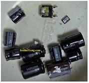
And, finally, these are the components that got replaced:
Anecdotes
Let me tell you all honestly that I love to work on my own sets, as I have the full freedom to do experiments and do whatever nonsense that comes to my mind! (LOL) In fact, I am so happy that I could share so much information on servicing an LCD Monitor and what are the alternative possibilities that we have, to make a stubborn defective set work! But, if it was a customer’s set, all these ‘out of bound’ experiments could not have been made! By the way, the crazy curiosity to work on sets within the home seems to be in the blood!
(My father was a Mechanical Engineer) I recall that during my childhood, my younger brother had the habit of experimenting with all medicines brought in, especially ointments. If we had bought Pain Balm, he would pretend to have it and get it applied. (He worked in Medical Field after graduation, and retired as a top Executive of a Pharmaceutical Company. He became such an expert in physiology, diseases, generic medicines that he took classes to even Doctors!) Similarly, I wished and if possible made things defective in the house so that I can open it and learn! Well, when I think of it now, I have grown only from bad to worse, in this habit! (LOL). The only difference is that I am now capable of fixing these up, whereas in my younger days, my success rate was as low as 40%! I quoted all these only to share the fact that in all our efforts the inborn talents are the real score fetcher! Goodbye until the next!
This article was prepared for you by Parasuraman Subramanian from India. He is 68 years old and has more than 30 years’ experience in handling antique equipment like Valve Radio, Amps, Reel Tape Recorders and currently studying latest tech-classes conducted by Kerala State Electronics Technicians’ Association. He has done graduation in BBA degree, private diploma in Radio Engineering and retired as MD of a USA company. Presently working as Consultant to Hospital and other institutions.
Please give a support by clicking on the social buttons below. Your feedback on the post is welcome. Please leave it in the comments.
P.S-If you enjoyed reading this, click here to subscribe to my blog (free subscription). That way, you’ll never miss a post. You can also forward this website link to your friends and colleagues-thanks!
You may check on his previous repair article below:
https://jestineyong.com/servicing-zebronics-atx-power-supply/
 (113)Dislikes
 (1)
(1)
26 Comments
Leave a Reply
Cancel reply


Andrea Del Corso
June 19, 2017 at 8:57 pm
Good job...thank for sharing.
Anwar Shiekh
June 19, 2017 at 10:04 pm
Messy work, why not install the capacitors properly and cutting tracks...
Parasuraman S
June 20, 2017 at 1:01 am
This is a very small board, with crammed components. Too much of heating will spoil the track as well as the nearest component or dis-align it. From my experience, I have learnt that it is better to cut the capacitor and solder new one on its stubs. This was also suggested by many in this forum as comments on my earlier articles! Yes, it is a bit messy, that is better than spoil!
Albert van Bemmelen
June 19, 2017 at 11:16 pm
I really enjoyed your very well written article Parasuraman Subramanian!
It also was a very interesting one too. The mentioned step-down-voltage replacement board is sure something to keep in mind when needed.
I take it that the mentioned Mosfet rating of +/- 50A, 120V (32 Ohms) is a typo because you probably meant a RDSon of 0.32 Ohm?
I wonder if the shorting step-down-regulator chip got really hot? It could have been a sign of being a bad working component?
Parasuraman
June 20, 2017 at 3:01 pm
No. As mentioned by me, the current drawn is only around 300mA. The voltage drop required is causing the problem. Pl study data link sent. Then you will get it!
mahmoud_tajpour
June 20, 2017 at 4:43 am
Hi dear Parasuraman thank very useful.
Anthony
June 20, 2017 at 5:40 am
Great repair and great outcome Parasuraman ! You were like a dog with a bone that wouldn't let go
until you solved the problem which is also as you explained for your own educational benefit. Nothing
wrong with that and it certainly paid off for you. Thanks for sharing your experience here !
Kind Regards
bons2damaks
June 20, 2017 at 5:43 am
thanks for sharing.good job
Robert Calk
June 20, 2017 at 6:06 am
Good job, Parasuraman. That is a lot of work and time spent for a monitor.
Gerald Musy
June 20, 2017 at 12:14 pm
Beautiful article Parasuraman. It reads like a good detective story, I enjoyed it. I envy your tenacity, as per Anthony's comment, you don't let the bone go.
Thanks for sharing
Cheers,
GM
ajay
June 20, 2017 at 1:07 pm
my acer lcd moniter having full white screen problm. many of the guidence say's that bad connection in the connection strips. and i double check all the connections. still promblem not solved. and also check for bulge capasitors. but can't find any thing.and i replaced a ceramic capasitor 1.1k from power section because it rust and non conducting. still the problem can't be solve. pls helpme.tks
Parasuraman
June 22, 2017 at 10:16 am
Try to get a schematic or service manual of the set. Mostly these are freely available for download. Check all voltages that go to Panel. Is sound OK? If so, the fault is video missing. There can be multiple reasons for it, right from video input socket to panel! The only way is to check voltages at various points right from secondary power regulators to T'Con Board!
Parasuraman
June 22, 2017 at 10:20 am
Sorry, I overlooked it was a monitor. So sound issue does not apply.
Robert Calk
June 23, 2017 at 5:13 am
Hi Ajay,
Have you checked the SMD fuse on the T-con board?
WAGESH VARMA
June 20, 2017 at 2:24 pm
THANKS SIR
Suranga Electronics
June 20, 2017 at 5:36 pm
MR. Parasuraman,
Very Nice and important Repair.
Thanks..!
Andrew F. Ali
June 20, 2017 at 8:01 pm
Nice article...I especially liked the piece of history at the end...Very Good..
James
June 21, 2017 at 3:09 am
Thank you for sharing your challenging experience, it helps us who are experimenters too and love hearing your knowledge from your own experiences.
Humberto
June 21, 2017 at 11:24 am
Good repair Mr. Parasuraman, you are a master
tom
June 21, 2017 at 9:17 pm
Good job Grand Pa
parashu ram singh
June 22, 2017 at 6:57 pm
thanks sir
i am very grateful to get update from different electronic equip as well as lcd/led. right now i am also very crazy about new era of electronices field and i am making our carrier in this field.
you are requested to kindly suggest me i this field is successful carier and depend it or not do advice me at once now i am computer literate and got master degree in this field but no much money in this field.
Parasuraman S
June 23, 2017 at 11:13 pm
It is the passion that you have or develop as you get along with your work, that decides the results. Every sincere and devoted work, whatever it might be, will be fetch results. Almost all successful men across the Globe have only this secret to share. Passion is the driving spirit! All other material benefits that you gather, are a byproduct of this 'passion'! Please spend time by being introspect, check within yourself what can drive you! Then choose your career accordingly. All qualifications we get are only filters for choice, and they cannot alone support us, unless we develop the drive. (To answer your question, if people are bringing sets to me from even US and faraway places like Delhi, Calcutta, Chennai, Hyderabad etc., it is only because of the recognition created by this passion!) All the best.
Yogesh Panchal
June 22, 2017 at 10:05 pm
Good Job! Sir.
Edward
July 9, 2017 at 10:59 am
I find it to be an excellent job; and I love love it.
Bibhas
July 26, 2017 at 5:22 am
very good job sir. it's like an investigation & solvation. plz tell the replaceing mosfet number. many thanks for shareing your idea.
Parasuraman S
July 30, 2017 at 2:39 pm
It is already there in the article!