
Tektronix 2440 Oscilloscope Repaired- Part 2

After my last article on a Tektronix 2440 Oscilloscope Repair was published:
https://www.jestineyong.com/tektronix-2440-oscilloscope-repair/
That had a Big Short Circuiting (Low Voltage) Power Supply that blew up the Wall Outlet Main Power Fuse, and its 600V 3A Fast Recovery Diode Bridge plus the Scope Mains input Fuse. I had to find the exact reason why the Scope still didn’t behave as it was supposed to. (The scope Screen was very jumpy that lateron turned out to be in Horizontal direction only).
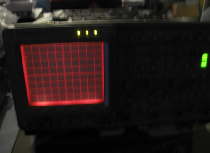
Above photo shows the Powering Up of the Tektronix 2440 Scope.
Although I brought the 2440 Scope Back to Life after fixing the dead Power Supply it probably still needed new Hybride parts. That was at least my first Impression. Or maybe a new Hybride Board. Because only the Intensity CRT tube potentiometer and the Scope Buttons did work. And it also had something to do with some problem on the 5Vd line from the Power Supply Board to the Hybride Board. Although the original F269 5Vd fuse (10A) was okay, just as all other Board Fuses , it seemed to be short circuiting this line somehow. And maybe also was the cause why the Diode Bridge got defect. The short was not on the Power Board itself! I checked this by connecting an external 5V Power Supply to 5Vd on the Power Board. And only when connector J102 to the other Boards was attached on the Power Board there was a very low Voltage of about 2.25 Volt. (I opened the Fuse F269 connection to 5Vd first of course!). And without J102 connected there was a stable 5.20 Volt on the Power Supply from the external Power Supply! The transformer coil AC voltage for the 5Vd line seemed with 9 V probably a bit too high. The dual rectifier diode for the 5Vd line to the F269 (10A)
Fuse was still fine however! So I did Fix the dead Power Supply but probably needed replacement Boards or new Parts to Fix the Tektronix 2440 Scope. And that all depended on the Price Tags. The 5V line voltage on the A12 Processor Board, measured over the TTL components, was Fine! So I was almost certain it couldn’t be this Board that was causing problems. Knowing the fact that these old but reliable Scopes were becoming very affordable by the day, it was only a question of waiting for the right moment to buy spare parts.
The Sytem I/O Board seemed to operate fine too! Because the Loudspeaker on it (that also was Powered from the +5Vd Power line) just like the 555 chip U274 that generated the sound, and U754 a 74LS273 that activated the three GPIB Leds mentioned in the article, all worked splendidly.
And I also checked following parts on the LV Power Supply Board : U265, U155 (optocouplers), U189AB, C455 (electrolyte 6,3 Volt), U829, U834, U470, U840 and Q295. And they all were perfect! Also I noticed that U100 and U150 were rather cold compared to the other Hybride Components on the A10 Board. And only the Voltages on the J166 connector to the CRT HV Board on pin 1 and 2 were out of spec. With being around -22,5 Volt. But because pin 2 is the -12V line to the Perfect working 12 Volt FAN it doesn’t have to be any real problem. And because I checked most if not all parts on the Power Supply it was not a big problem that also the previous mentioned Unregulated +5Vd with being about 6,7 Volt (unloaded) was a bit higher than the given 5.12 Volt in the LV Power Circuit. Because it had to be a small Power Supply problem because all tested parts were fine!
I then found new evidence that hopefully helped to fix my friend’s 2440 Oscilloscope.
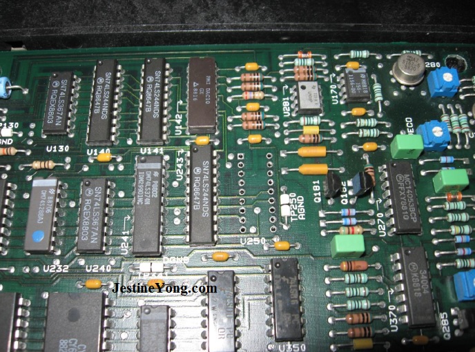
Photo above shows the A11 Board with the removed Bad PMI DAC10 chip. Chip U142 is the other DAC10 responsible for the Vertical deflection on the CRT tube.
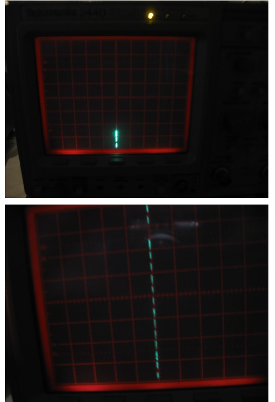
Not soon after I found the probable cause of the bad working Tektronix 2440 on the A11 (Display+ more) Board: A bad working PMI DAC10 chip (got very hot!) that had to be for the Bad working horizontal CRT screen deflection. After I removed this about 30 year old chip the CRT produced a very stable and clean vertical line of scope data. That changed its data when I pressed some of the Scope Front Buttons.
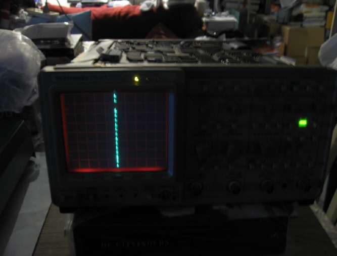
Above photo shows the result after DAC10/U250 was removed. No Horizontal deflection.
So I ordered 1x PMI DAC10 chip on Ebay from a seller in the UK for 19.80 euro’s (about 13.99 English Pound). And I was very curious if the scope would operate as new again after the U250 DAC10 chip was replaced. These chips are also at least 30 years or so old. So I’m happy to have found one. The other DAC10 (U142 on the same Board) is for the Vertical deflection and must be perfect because the vertical written data line on the Tube was nice and clear !! After questions from other Jestine’s Repair Blog Readers, I had to make a follow up on the previous article, depending on the fact if the Scope would work after the DAC10 was replaced. So I had to wait until this component got here.
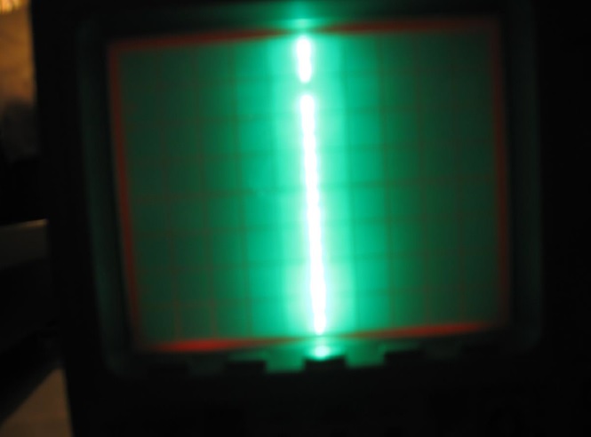
Next photo clearly shows that the CRT Brightness easily can be adjusted to much higher Intensity.
After these facts were noted, I also checked if the FAN voltage on the J166-pin2 to the HV Supply CRT Board was within spec. Because the open/unloaded Voltage of -22.5 Volt was just too high. But luckily it was okay because I measured exactly -13,7 on the Black Fan wire when the cable to connector J166 was connected. REMARK! What I didn’t know at that earlier time was that the Scope’s LV Power Supply gives wrong higher Output Voltages when no correct Loads are connected at all. (So I had checked all important components that were involved in regulating the 5Vd output on the LV Power Supply for nothing. But that was also when the Bad DAC10/U250 still was causing a short on the Power Supply’s 5Vd line and constantly interfered with the Scope’s screen output. And why even an external 5V Power Supply collapsed to only about +2.25V when connected to the 5Vd line. Although the energy overconsuming Bad PMI DAC10 probably doesn’t use any +5V for powering itself. And probably never an unregulated 5Vd voltage either).
But after this problem was solved, I finally measured last but not least, that the 5Vd Power line was exactly 5.13 Volt. (Was earlier unloaded a bit too high to with about 6.7 Volt measured).
Next photo shows a Close-up of the CRT screen when less data is displayed. Only the bottom lines are vertical showing up.
And the photo that follows shows the CRT screen when it displays a lot of data lines.
To be sure that a new DAC10 would work, I also measured the Voltages on the DAC10/U250 pcb socket. V- (on pin 3) was exactly -15V, V+ (on pin 15) was +15 so perfectly Fine! (a DAC10 works upto Max. Voltage of +/-18Volt!).
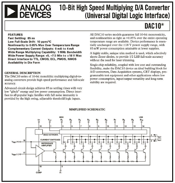
Next Picture shows the first page of the DAC10 datasheet:
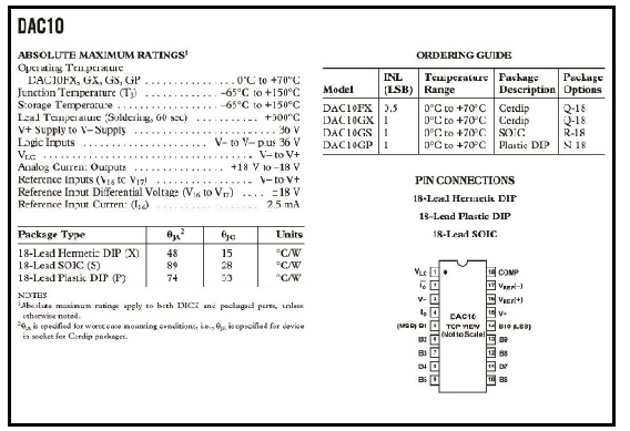
Above picture shows the 18 PINs layout of the PMI DAC10 extracted from the datasheet.
So I was very certain the Tektronix 2440 Oscilloscope would be as new after replacing U250, and the already replaced CR510 Diode Bridge and the 4A/250V Mains Fuse. And the Short Current that dropped the 5Vd output Voltage level was now completely gone. All Voltages on the Power Supply Board were now within exact Specifications ! (But again only after the Power Supply J102 was
connected to all Boards!! Open Voltages on this Board are Higher!). So the LV Power Supply Board is completely working as a brandnew Board again ! Replacement costs of this complete Tektronix repair is only about 25 Euro. With the fantastic Help of the terrific Tektronix Service documentary that is Free available on the WWW.
PCB copper connections/track Layouts are however never given. Only the Schematics with Scope Diagrams. But it is very clear visible and understandable Information. So any PCB/Board has to be in splendid condition. A Very Big applause to the fantastic Tektronix Scope Designers!!. (Keep in mind that all Tek Service Manuals often also have a Manual Change Report at the end of their Manual that give Diagram Changes depending on the Serial Numbers of the Manufactured Scopes. Right after the standard Replaceable Electrical Parts List, the Replaceable Mechanical Part List, the splendid TroubleShooting Diagrams and of course the in their function very well catagorized Schematics).
To give an example of a change that has been made to this 2440 oscilloscope serie : The old Diode Bridge CR510 on the LV Power Supply is in newer models replaced by 4 single Fast Recovery 600V Diodes.
And knowing these Tektronix 2440 Oscilloscopes still cost at least around 300 to 400 US dollar today, my friend has a real bargain after my repair if the scope is re-calibrated. Although this Tektronix 2440 Oscilloscope has a Bandwidth of 300 MHz, also remember that presumably all of these Tektronix Scopes easily are capable of measuring frequencies that are twice their Maximum Bandwidth. At least that’s what I keep reading on several Forums about these great Scopes. My own recently in Texas bought Tektronix 2465A has no GPIB interface like this 2440 does. And my friend’s 2440 Scope is build around 1988 because that year can be seen on many components on the pcb Boards. (And that makes it about 2 years younger compared to my own 2465A 4 channel 350 MHz Tektronix Scope- that had already 48873 working Hours on it’s internal Diagnostic Counter and was switched on a total of 1596 times in about 30 years. The Lithium Battery in my Tektronix 2465A was dated 2486. Which I already replaced about 3 months ago with the help of the splended replacement article Published by Robert Calc on Jestine’s Repair Blog about 6 months or so ago).
Next photos show the result of the 2440 Tektronics CRT screen after I replaced the Bad DAC10 U250 by a new one. As the built-in Self-Diagnostics now clearly shows there are still some Failures found at Start-Up. But now the Scope really works again and I’ve obviously also Fixed the CRT display problem to enable further Diagnostic. Because without a working screen it is almost impossible to find what is wrong with the Oscilloscope’s internal electronics. It would be a too complicated task without the Self-Diagnostic Built-in Test.
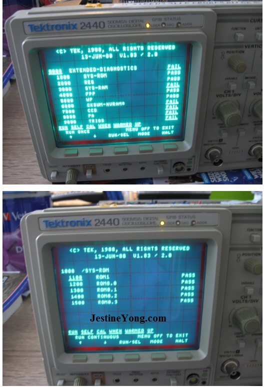
As Diagnostic clearly shows, there’s nothing wrong with the Eprom content of the Roms in the 2440.
This 2440 Oscilloscope even has at least 4 CCD (Charge Coupled Devices) Memory modules on Board, besides the regular RAM chips. And probably one or more modules now fail. According to the 6 presented Fail Messages on the CRT.
But the 2440 also has AUTOFOCUS on the HV CRT Board in a 20 pins IC (U227 in the HV Supply & CRT Schematic) with tektronix List number 155-0294-00 (on Ebay about 18 US dollar). And that works perfectly! My own 2465A Oscilloscope doesn’t use a PMI DAC 10 for the Vertical or the Horizontal Scope Deflection. And probably no CCD devices, since the 2440 Tektronix is a Memory (hence the 500MS/s) Oscilloscope which my 2465A isn’t. But my 2465A uses another and totally different U800 chip that gets at least 50 degrees Celsius according to the Tektronics Forums.
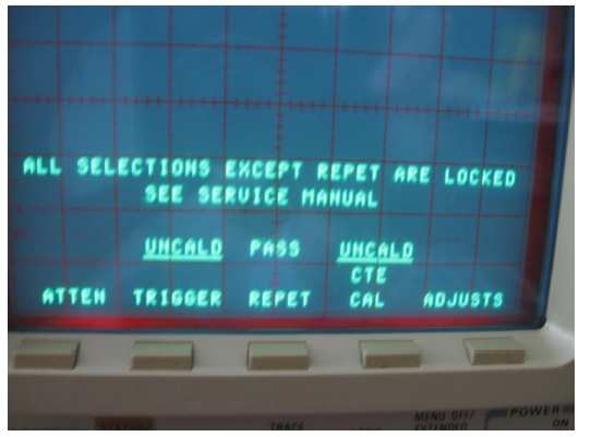
After I played a bit with the Front Buttons on the outside of the CRT, I got following message (see next photo) that all selections would be locked apart from Repeat. And that I now had to look into the Service Manual. Since only Calibrating costs about $ 600 US dollar and I do not have other replacemant parts like CCD-Modules, I guess that here my 2440 journey ends. At least until I find new replacement parts.
Summarizing I can only advise any reader to also try to repair any decent Tektronix Oscilloscope, even if these devices are of some age, because they are very nicely build and the service manuals are very helpfull. Of course as long as spare parts are still available! Or buy at least a Tektronix Scope that does not fail on the Internal Build-in Diagnostic Test. Which presents itself at Start-up/Powering Up. Like the Seller had assured me before I bought my 2465A Tek. Ask the Seller of the Oscilloscope
at least what this Diagnostics Test tells him, and how many Hours it already had operated in its electronic lifetime. Because that’s something that also gives any Tektronix something extra over any other Oscilloscope!
I hope you all had just as much fun with this repair as I had!
Until another repair, or a new interesting electronics article.
(And yes Frans, I will shave but another time, I had to fix your Oscilloscope first! LOL)
Albert van Bemmelen. Weert, The Netherlands.
Please give a support by clicking on the social buttons below. Your feedback on the post is welcome. Please leave it in the comments.
P.S- If you enjoyed reading this, click here to subscribe to my blog (free subscription). That way, you’ll never miss a post. You can also forward this website link to your friends and colleagues-thanks!
Note: You can read his previous repair article below:
https://www.jestineyong.com/kodak-photoprinter-repair/
 (85)Dislikes
 (0)
(0)
19 Comments
Leave a Reply
Cancel reply


Muhammad Akhlaq
September 30, 2015 at 6:27 pm
Very fantastic article on oscilloscope repair... Keep it up. Waiting for more.
Albert van Bemmelen
September 30, 2015 at 11:47 pm
Thank you Mr. Muhammad Akhlaq. I'm glad that you liked it.
Maybe next part#3 about Calibrating this great Tektronix 2440 Oscilloscope is also of interest to you? After the first few Calibrating steps there the 2440 is really working.
Robert Calk
September 30, 2015 at 10:06 pm
Thanks Albert. I wonder if your friend blew his scope by having the ground of the power supply supplying power to the DUT on the same ground plane of his scope? He should go to YouTube and type in, "How not to blow up your oscilloscope".
Also, thanks for mentioning my article.
Albert van Bemmelen
September 30, 2015 at 11:42 pm
Hi Robert. My friend Frans got this Oscilloscope from a radio amateur who owns his own business and simply gave it away for free after it blew up the primary fuses of the Oscilloscope and the AC Power Line at Home. And since it went out of order he had no longer use for it. And my friend Frans, nor his friend did make the mistake you mentioned because it all probably happened after the PMI DAC10 chip short circuited somehow. After which the Diode Bridge short circuited also between the - and ~ pins.
aziz
October 1, 2015 at 1:28 pm
Thank you
Yogesh Panchal
October 2, 2015 at 3:15 pm
Sir,
Thanks for informative article.
Hicham
October 3, 2015 at 2:15 am
Hi Albert,
how you test other circuits by simulation method or with some particular tester?
please give me some details on this! cause your behaviour method with the pcb it's so interesting for me to know also in order to uplift my skills level of repair.
Thanks Sir.
Albert van Bemmelen
October 4, 2015 at 1:38 am
Hi Mr.Hicham. As I may have written before I use one or a few of my Digital Testers I have to check the Integrated Circuits like Optocouplers, Opamps, Transistors, Mosfets, or Diodes.
The easiest way to be sure they are okay is to solder them out of the pcb, but of course only the parts that I suspect to be the cause of a malfunction. I first look in the schematics to be able to confirm if they are involved in the problem that needs to be solved.
I have a few portable Universal Digital testers from Ebay for this. And also a Genius G540 universal programmer that also can read and write parts like TTL/CMOS IC's and also components like BIOS flashable Eeproms. But I first look on PCB's for any burnt or strange marks/spots that indicate that a component is defect. And if there is no dangerous Voltage on the Board I also use my fingers and nose, to tell if something gets real hot or gets cooked. And of course a universal Voltage/Current/Resistance Digital Meter is a Electronics Engineer's best used device for measurements.
Hicham
October 4, 2015 at 10:36 pm
Hi Mr Albert. seriously you are the best professionel working with certain efficient method. also i like your article hoping to share with us more your knowledge.
in fact i notice that the best way to check suspect components only by this V/i like a huntron, so that's why i will use soon and design one octopus for my oscilloscope.
So i tell you big thanks to you for your answer and effort explanation. the same to not forget, i also pass my thanks to Mr YONG Jestine who have a excellent role with our team.
Best Regards
Albert van Bemmelen
October 7, 2015 at 12:14 am
Indeed we all owe a lot of thanks to Mr. Jestine Yong who maybe has one of the Best, if not The Best Internet Electronics Repair Site in the World.
And he soon will publish the Final part#4 of this 2440 Tektronix Oscilloscope Repair article. That article shows how to save $600 dollar on Calibrating Costs after which the Oscilloscope will be completely Fixed and Ready!
So if you liked the previous articles, there is more to come Mr. Hicham. And I must add that although I have many Electronic Analog & Digital Instruments, like 4 Oscilloscopes etc., the Digital Universal Multimeter is still always my best used instrument. (Such as the Semiconductor Diode test, Voltage test. And like anyone I suppose the Current measurement is used less frequently). And before you measure anything you always better think, what and why you want to measure and always how you can do it safely. (for yourself and your components).
Albert van Bemmelen
October 7, 2015 at 2:28 pm
By-the-way: I also do have a original Hameg HZ65 Component tester that works similar like the Huntron Testdevice you mentioned. But the thing with these kind of testers is that you likely do need to compare the curve of a presumably Bad Semiconductor with the one of a second Semiconductor V/i curve that you know is still 100% OKAY. So you probably never can be very sure when you test on a Bad working Device. Because the Testcables also influence the way how the Scopecurve is displayed.
Humberto
October 7, 2015 at 10:54 pm
Hi Albert, good photos and explanations. Keep up.
Albert van Bemmelen
October 9, 2015 at 4:58 am
Thanks Humberto. I just fixed some new repairs.
Albert van Bemmelen
April 10, 2021 at 5:16 pm
Today 10 April '21 I was successfully able to copy the 4464 8192Bytes (8K) SRAM in my Tektronix 2465A oscilloscope that also contains all Calibration data.
I modified my 28 pin testclamp with 28 pins socket and used my TL866II as 27c64 eprom reader to extract the content of my RAM as bin copy. Simply by adding a 1N4148 diode to Vcc of the 28 pins socket this way accidentally avoiding losing the backup lithium voltage on pin 28 of the 4464 static RAM while starting to read it. And added two 100 ohm resistors to pin 27 (/PGM) and pin 26 (nc on 27c64 but CE on the 4464!) are pullups to prevent accidentally writing instead reading the SRAM. (both wires from testclamp to the 28 pins socket therefore can be left unconnected). But therefore you also disable the pin contact test in the TL866II program and do not need the chip ID check either. And after reading the Ram also verify it to make sure it was read correctly without errors! I already ordered 2 FM16w08 special Ferromagnetic RAMs that never lose their data even without any Lithium backup voltage present. One will be used to replace the 4464 in my 2465A scope the other will be used in my 2440 as soon I've also successfully backupped that SRAM. And because the square pins on the 16w08 to DIP adapter board are too thick for the standard IC sockets to be insreted into the scope SRAM position I also ordered 2 ZeroForce 28 pins 3M textool sockets that easily fit into the mainboard.
Albert van Bemmelen
April 10, 2021 at 10:59 pm
Update: The Tektronix 2440 SRAMS are HM62256 32KB type rams that require the special FM1808-70-PG ferro magnetic memory chips instead the FM16w08 (or the FM1608 DIP) that have 4 times more memory capacity compared to the original DS1230 32K chips often used in the 2440 memory oscilloscope. I was able to buy 2 FM1808s DIP on eBay for only US$5.89 (about 4,95 Euro). And they have a worry free retention time of 10 years without the need of any dangerous lithium backup battery. That also can leak in time! The above mentioned testclip with 28 pins socket cable can still be used after pin 26 is reattached to the testclip and its 100 ohm pullup is removed because it here is addressline A13 instead of the CE pin it was on the 4464 SRAM.
Albert van Bemmelen
April 10, 2021 at 11:16 pm
PS: there is no need to remove any of the databuffer chips or the CPU to be able to read the data in the 4464 SRAM because if the scope is powered off there is no address or databus line conflict since at that moment the Sram will be the only functioning component in the 2465A (or the 2440 or other equally designed Tektronix) scope!
Albert van Bemmelen
April 12, 2021 at 9:14 pm
Warning! Although the 62256 SRAMS in the Tek 2440 scope look exactly easy IN-CIRCUIT READABLE as the 4464 SRAM does that also is only connected to the Backup Keeper Lithium Battery in the 2465A scope if the scope is powered off (meaning no data- or addressbus conflict!). However reading the calibration data from the Tek 2440 SRAM chip completely failed verify wise. I made a special 28 pins 27c256 eprom to 28 pins 62256 testclip reader cable and attached it to my TL866II and after that also with my G540 universal programmer. But both failed to read the data without any read error! And afterwards I needed to SELF CALIBRATE the 2440 like explained in this repair article. But I again was able to PASS all previous scope errors that occur when the NVRAM or the calibration in it was corrupted. Which now still only leaves the External Calibration (Ext Cal) procedure that is at fault and just requires removing a jumper on the scope's mainboard and manually calibrate the scope's inputs by providing a few good calibrated signals to setup the internal CCD memory and adjust the amplifier values in NVRAM.
Albert van Bemmelen
April 11, 2021 at 4:18 pm
In the Tektronix 2440 memory oscilloscope the SRAMs are type 62256 32K memory chips. And they can be replaced by Ferro magnetic chips type FM1808 28DIP memory chips that without the need of any Lithium backup battery hold their data for at least 10 years (retention time 10 years)! Only the SRAM positioned at U664 stores the calibration data and better needs this FerroMagnetic chip calibration safety upgrade.
Albert van Bemmelen
April 18, 2021 at 1:09 am
Update: Programming the RAMTRON FerroMagnetic FM16w08 chips for my Tektronix 2465A scope with the brandnew TL866II is simply impossible! Although they are supported in the device list the universal programmer sadly kept giving at least 24 verify errors. And also a second brandnew FM16w08 failed in the same way!
Luckily my RT809H was completely capable to program, read and verify both memory chips perfectly! But only after I upgraded the windows program to new version 20210222. Because previous RT809H version only supported the FM1808 type for my 2440 Tek scope.