
Using Clear Schematic Diagram To Troubleshoot Desktop Computer 400W ATX SMPS
I received call from the customer that his computer does not turn ON & He has confirmed problem with SMPS because he is having card level repair experience. So I request him to send the SMPS to my place for repair.

On arrival SMPS connected to the series Bulb Board bulb does not light up no sign of Life. So for further inspection I opened the SMPS.
Found full of dust under the PCB. First of all discharged the Mains capacitors for safety then Cleaned the PCB.
After cleaning work it now time for Visual Inspection I found One Main Capacitor Bulged. Except this Capacitor I didn’t found any sign of physically damage.
We found no sign of the Life in the SMPS so first suspect is fuse. Checked Fuse for burnout sign but visual it seems Ok. Checked Continuity on fuse found Ok. With this result it is confirmed that there is no short circuit on this SMPS. So decided to do some voltage testing…………. (Be careful for Live voltage testing High 320V Voltage are available on Mains Capacitor)
- Checked voltages on mains capacitor separately it shows 160V DC as this both capacitor are connected in series we get 320V DC directly going to mains Switching Transformer & On Drain of both the MosFet on primary section.
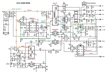
For easy understanding about the voltage path find Reference Circuit diagram Of ATX SMPS as follows. There is no voltage found on Gate of both the MosFet for switching. Next Checked VCC Supply on PWN IC UC 3843 pin no.7 there is no supply. Checked for 5V DC Stand by Voltage Near stand by transformer Diode No Voltage. That means there is something wrong in PWM stage?????……………….
This Circuit Diagram is applicable to most of ATX Computer Power supply. Here is pin out and reference Voltages on PWM IC.
So first step is to replace the mains Capacitor & check for the Result
After replacing the capacitor again I did some voltage testing but problem is not solved. Removed some other parts from the PCB for checking.
Checked other small parts also but everything seems OK. Exhausted in process to understand the circuit operation. Because not having proper circuit diagram. So I kept everything on side for next day job. Next day Morning I have again on the mission.
Now I have focused my attention on standby circuit only because for switching process this Voltage is required. So first of all what I have done i make standby stage component location diagram on paper and right down Value of each resistors so that it will save time for fault finding and doesn’t escape any component for testing by mistake.
After making this diagram I have again started testing the components one by one. Here is what I have escaped the component for testing is 470KΩ Resistor just above the Stand by transformer. Resistor is showing around 430Ω on the circuit but when I checked it out of the circuit it is not showing any reading means this resistor is open circuit.
I have arranged the working resistor for my salvage collection and I replaced on the circuit. After replacing resistor I powered on the SMPS and now I can see ATX Exhaust fan is spinning.
Connected the smps on tester…………….
SMPS is working Ok .Now mission is complete………………………………. & Here is the role of the resistor in the Circuit.
Stand by MosFet Getting Driving Gate voltage directly from 320V DC Line (Mains Capacitor) and going to MosFet gate using two Resistors 470KΩ & 22KΩ. Out of them 470KΩ found open circuit as marked on the component diagram.
When Standby MosFet starts switching, Stand by transformer starts Oscillating and from the standby transformer secondary side gives 5V standby supply Voltage to one Opto coupler and opto coupler is giving O/p to the base of one transistor and that transistor is produce VCC supply for PWM IC on pin no.7 and by pin no. 6 it gives triggering gate Voltages to Main Switching MosFet and it start switching & main transformer produce O/p Voltages on secondary side of the Circuit.
This article was prepared for you by Yogesh Panchal who works as a Computer Hardware Engineer in Mumbai India.
P.S- Do you know of any your friends who would benefit from this content that you are reading now? If so, forward this website to your friends or you can invite your friends to subscribe to my newsletter for free in this Link.
Note: You can check his previous repair articles in the link below:
https://jestineyong.com/creative-sbs-370-2-1-speaker-modifications/
 (82)Dislikes
 (1)
(1)
22 Comments
Leave a Reply


Parasuraman S
March 4, 2021 at 5:29 pm
Very methodical approch and solution! Excellent! Many thanks for sharing!
Yogesh Panchal
March 8, 2021 at 9:38 pm
Thank you! Sir,
MARINKO
March 4, 2021 at 8:35 pm
Marinko:
Many thanks for sharing!
Yogesh Panchal
March 8, 2021 at 9:39 pm
MARINKO,
Your Welcome!
Albert van Bemmelen
March 4, 2021 at 9:18 pm
Nice work!! I suppose that your power supply tester has no real loads to make sure every power supply is adequately tested either? And in some cases it likely will fail in correctly test the higher desktop powersupplies. Thanks for sharing the schematic which shows a 230VAC desktop unit that uses two primary 200V main capacitors in serie. Like the earlier desktop power supplies that also had a voltage selector switch to be able to select 115 VAC input by only using one of both main capacitors while shorting the other in serie placed capacitor.
Yogesh Panchal
March 8, 2021 at 9:44 pm
Albert,
I didn't checked the tester yet by opening.for loading SMPS i think 12V car signal light incandescence bulb will do the best.
HECTOR DELATORRE
March 4, 2021 at 10:05 pm
Good explanation on your part, keep the good articles coming.
Yogesh Panchal
March 8, 2021 at 10:04 pm
HECTOR DELATORRE,
Thanks! for the comment.
Henrique J. G. Ulbrich
March 4, 2021 at 10:38 pm
Very, very good, Yogesh. a profound analysis. It´s very productive for us to understand when the article includes a circuit diagram. I understood from you that this is not the exact diagram of the SMPS you were servicing. But it helped a lot in understanding. Do you have the link for this SMPS circuit diagram?
Yogesh Panchal
March 8, 2021 at 10:12 pm
Henrique J. G. Ulbrich
Thanks! for your comment,Shared diagram is just for reference because i didn't found the same circuit diagram.But from this diagram you can easily understand stagewise working of the SMPS.
tino
March 4, 2021 at 10:40 pm
excellent job
Yogesh Panchal
March 8, 2021 at 10:13 pm
Thanks! tino.
Babu M S
March 4, 2021 at 10:44 pm
Very good job.Many thanks for sharing
Yogesh Panchal
March 8, 2021 at 10:13 pm
Your welcome! Babu M S.
William Shaw
March 5, 2021 at 4:42 am
Excellent work!
Yogesh Panchal
March 8, 2021 at 10:14 pm
Thanks! William Shaw
Arnel G Cartoneros
March 5, 2021 at 7:33 pm
Thanks for sharing sir, nice post great learning.
Yogesh Panchal
March 8, 2021 at 10:15 pm
Arnel G Cartoneros,
Your Welcome!
Humberto
April 2, 2021 at 12:31 am
Excelent job, congratulations.
Imsa Naga
August 15, 2021 at 2:49 am
Great Tutorial for Hobbyist and Professionals alike...
would it be possible to increase the +12V to 24/36 Volts ?
if possible can you be kind enough to explain with schematics ?
Thank you in anticipation.
S Karmakar
January 17, 2022 at 2:21 am
Sir, can you share circuit diagram of Frontech 400W SMPS Model no. JIL-2411 ?
Two resistors on primary side, connected with optocoupler EL-817 have burned and I am unable to see their values.
One resistor is connected with pin 3 of EL-817. That pin is also connected with base of transistor C945.
Another resistor is connected with pin 4. There is a zener diode in series on the other side of this resistor.
Mahinda Coomasaru
March 8, 2022 at 5:46 pm
Good explanation. Thank you so much.