
Voltage Testing Points Of Mobile Charger
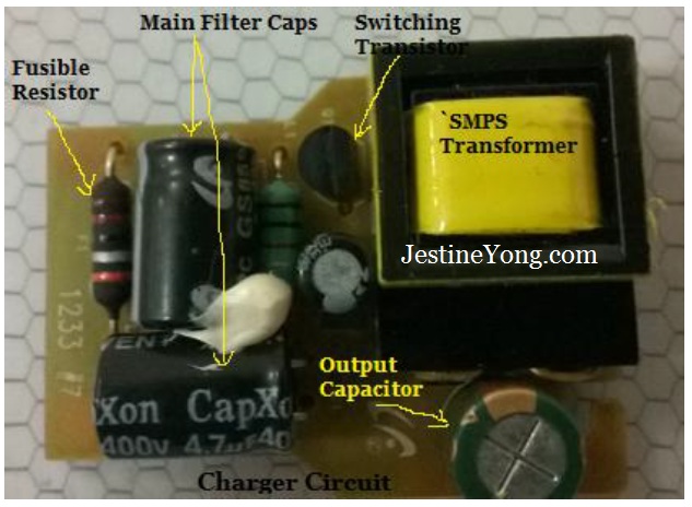
Today’s topic is about voltage test points (TP) in Mobile Phone Charger. The below pictures are the marking of the components:

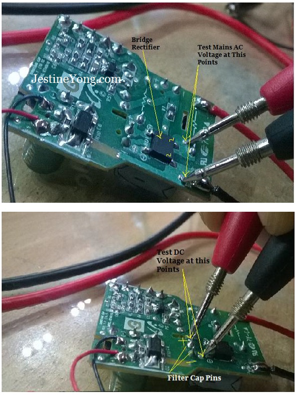
First connect the charger to the Main AC Voltage. Make sure the AC voltage is coming out from an Isolation Transformer.
After that select AC voltage range in Multimeter and place the meter probes onto AC input points on Bridge Rectifier as shown in the below picture.
If you have an Oscilloscope you can use it to check the IC output pin or Transistor Collector /Drain pin.
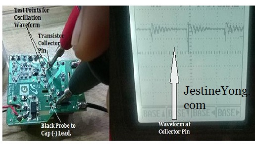
If you are using a normal Oscilloscope, make sure it is connected to an Isolation Transformer otherwise it may trip the whole floor. In my case I used handheld battery operated Oscilloscope. As you can see in above picture the Oscilloscope was showing PWM signals waveforms so it means that the Power IC generates proper waveform and its working. Your next test point should be secondary side output pins as seen in below picture.
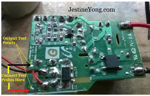
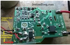
You should get output 5VDC when you connect your meter test probes on above mentioned test points. If you did not get the output voltage it means there could be problem and you need to troubleshoot the circuit.
Conclusion- Every electronics circuit board must have test points and you need to locate these points to help isolate the fault fast. In the beginning you may need schematic diagram to assist in finding the test points. Once you have grasp hold on this technique you can automatically locate test points in any circuit board in very less time thus it will speed up your troubleshooting work.
This article was prepared for you by Owais Akhter from Muscat Oman.
Please give a support by clicking on the social buttons below. Your feedback on the post is welcome. Please leave it in the comments. By the way if you have any good repair article that you want me to publish in this blog please do contact me HERE.
 (229)Dislikes
 (0)
(0)
19 Comments
Leave a Reply
Cancel reply


Sanan
August 18, 2014 at 12:34 pm
Could you please advice on which handheld oscilloscope do you use?
wael fathe
August 18, 2014 at 6:08 pm
this was the ut81b from uni-t
Atish Chand
August 18, 2014 at 12:38 pm
Brilliant
yogesh panchal
August 18, 2014 at 2:19 pm
good explanation keep it up .
marwan
August 18, 2014 at 3:53 pm
Very good
Oswald
August 21, 2014 at 9:16 am
since the first time I heard about you and kent liew I've been a supporter, please keep up the good work.Job well done
wael fathe
August 18, 2014 at 6:06 pm
JESTINE i have question for you and all techs here i do have the same scope shown here it is the ub81 from uni-t i have used it because it neeeds no isolation transformer when used to probe for the pwm in the primary side in a smps but now manner what power supply type i used to work on the pwm is not appear as square wave how ever the pwm appear alsways as square wave when i probe inverter ic pwm chip which is tested in relative to
cold ground
kiet le
August 19, 2014 at 6:09 am
very nice. thanks
Andre Gopee
August 19, 2014 at 10:27 am
Excellent points... Also in Mr. Jestine SMPS e-book has excellent on test points for these type of jobs.
Taring K Arioka
August 19, 2014 at 11:04 am
Good article thanks for sharing with us all.
K SGoh
August 20, 2014 at 1:06 pm
It was a good thing to mention passing the primary side through an isolation transformer as working with SMPS could be potentially lethal.
Even so, it would have been better if the board was secured/clamped down and the test leads insulated with as little exposed metallic parts as possible except for the tips.
owais akhter
August 20, 2014 at 3:30 pm
Dear Wael,
Soon i'll send pictures of PWM waveform of TL494 IC and you'll see that this is same waveform which you expected.
owais akhter
August 20, 2014 at 3:37 pm
Dear Wael,
You should put your scope's positive probe to power FET/Transistor Drain/collector pin and negative probe to Hot ground or big filter capacitor's negative lead.
Vasikr Petrica
August 21, 2014 at 3:50 am
Good job!Thank you!
Vasile Petrica
August 21, 2014 at 3:52 am
.....because speed!
dicksy
August 22, 2014 at 8:26 pm
good n nice article.
thanx
shahid ahmada
August 26, 2014 at 4:40 am
very goood
Raymundo Saura
August 27, 2014 at 4:33 pm
nice one sir thanks
Gurpreet
August 6, 2015 at 6:02 pm
Hello
Good job as well as good efforts to understand others also.
Thanks