
Wiring Broom- A Useful Short Circuit Tool
Today I run into a strange situation until I repaired an ECU from a car. Actually the car has a problem with controlling of one injector. The output voltage on the injector which is triggered by the ECU is half of the desired voltage of 12V. Something is in short or bad component are there inside the ECU who acts as a voltage divider.
I desired to open the ECU and start to investigate. Ok, I figured out does the pin50 from the connector of the ECU is going to the injector, but where is that pin 50 connected in the ECU?
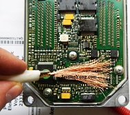
When I opened the ECU, in leak of the ECU schematic I started to trace the connection from pin50 to all other components legs with my multimeter, maybe I can figure out from where the signal is coming to the pin50. But, in short time I figured out does this method of searching will take too much time, and time is for me money. So I decide to make a tool with which I can faster find the trace from the pin50 to the other components.
Actually, with this wiring broom I can find the region where the trace is going, that is also good enough for me, if I know just the region where my DMM was beeped than I have to check several components and I will find the trace.
Here are the pictures:

I hope, you got the point of this tool.
This article was prepared for you by Christian Robert Adzic from Novi Knezevac-Serbia.
Please give a support by clicking on the social buttons below. Your feedback on the post is welcome. Please leave it in the comments.
P.S- If you enjoyed reading this, click here to subscribe to my blog (free subscription). That way, you’ll never miss a post. You can also forward this website link to your friends and colleagues-thanks!
Note: You can check his previous post in the below link:
https://jestineyong.com/exhaust-gas-recirculation-egr-system-hack-on-1-6tdi-engines/
 (123)Dislikes
 (4)
(4)
24 Comments
Leave a Reply
Cancel reply


Bernie Scott
February 27, 2017 at 11:12 pm
Nice idea.....Did you find your problem by using this??? if so, how long did it take to find the problem component......
Chris
February 28, 2017 at 10:16 pm
Hi! Bernie,
Yes, I found the problem and I also found the problematic IC and I will make a block diagram of the problematic L9135PD IC for what I found nowhere any datasheet or any explanation of the pinout etc.
I will send the debugged IC block diagram with pinout description to Mr. Yong, maybe he is interested to share with the rest of the world, because this info is really unique.
The time for searching for the short and trace from the pin50 to the IC and other component? He he, maybe in less than 5sec.
BAT!!! Be warned!
NEVER USE THIS TOOL ON A POWERED ON CIRCUIT!!!
ALWAYS DISCONNECT THE PCB FROM ELECTRIC SOURCE AND IF THERE ARE SOME
BIG CAPACITORS DISCHARGE THEM BEFORE!!
Zibbo
February 28, 2017 at 12:42 am
Brilliant Tool! Thank you very much for sharing this.
Albert van Bemmelen
February 28, 2017 at 1:23 am
That sure is another inventive way to search for the right boardcontact Christian Robert!
And a lot quicker and safer than using the testleads of a digital meter! As long as the ECU Board isn't varnished with a top layer against moisture.
Chris
February 28, 2017 at 10:18 pm
Hi Albert!
I'm agree with you fully!
My best regards.
Humberto
February 28, 2017 at 1:33 am
Hi Chris, and thanks for sharing your ideas.
Amendar
February 28, 2017 at 3:48 am
Hi man,
Its just the talent, using simple tools to solve big problems.
Thanks for sharing.
Alphonsus Lim
February 28, 2017 at 5:54 am
Very smart Christian Robert Adzic!
A quick way to narrow down leakage.
Mark
February 28, 2017 at 7:09 am
Brilliant idea - well done on your inventiveness!
Ulises Aguilar Pazzani
February 28, 2017 at 11:11 am
Hi Chris, great idea thks for sharing
Yogesh Panchal
February 28, 2017 at 3:55 pm
Chris!
Congratulations! for new tool invention.
Francis Egware
February 28, 2017 at 6:19 pm
I am encouraged by this article .Another way of troubleshootng faster . Many thanks guys for all your contribution .
Henrique Jorge Guimarães Ulbrich
February 28, 2017 at 11:06 pm
Simple and effective. Congratulations, Christian
Peter O
March 1, 2017 at 12:14 pm
I get it that this serves as a DMM "multiprobe".
But as a beginner I'd prefer a simple & detailed explanation of how to use the tool.
Please remember there are lots of novices following these posts, & not all will be prepared to ask
Chris
March 1, 2017 at 8:25 pm
Hi Peter!
So, here is a simple tutorial how to use the tool:
Make the tool as I wrote, set your DMM to continuity mode ( that is the section where the DMM is beeping when you touch the two end's of a wire withe probe) and connect one probe to let's say to pin 1 on a desired IC and with the broom start to move the wire broom over the pcb and search for a beep sound. If the DMM gives a beep sound you found a region where the pin 1 is connected and start to check the region without the broom with the single probe.
I hope this will make think's more clear.
My best regards.
Mohammed Kasim
March 2, 2017 at 11:42 pm
Very good idea. Thanks for sharing the information. I used lot of time for searching the track. This will be usefull for me in future
Robert Calk
March 4, 2017 at 7:32 am
Thanks, Christian. What is the output voltage of your DMM in continuity mode? It might be too much in some circuits. Are the IC's in automotive circuits all made to handle 12 volts?
Chris
March 6, 2017 at 1:53 am
Hi!
I'm a bit confused now about your question's.
The DMM's voltage output in continuity mode should not be more than 3v.
So mine has also 3v output.
For any IC's so in automotive circuits too the powering voltage should be in some way stabilized for what takes care the stabilizer IC and/or circuit inside the lets say ecu. There are no way to power up an ic through the live 12v power rail in the car, I mean not because the IC maybe can't handle that voltage but a voltage drop from 1-2 volt would be catastrophic for an eerpom or flash memory. They need stabilized voltages, in most of case it is 5V and 3.3V or very rarely 3V.
So, I'm confused with your questions because I don't see any relation with 12V in continuity mode of the DMM and also my article is usable on any circuit no matter if the circuit is powered from 12v ol 220v until you take care with capacitors etc...
My best regards.
Robert Calk
March 7, 2017 at 6:08 am
Hi Christian,
Well, on continuity mode, my Brymen 869s outputs 2.943V, my UT139C - 1.002V, and my Fluke 87V - 7.321V. I'm just thinking that people should know the output of their meter or in some circuits they may do harm to some IC's.
Zed Pato
March 4, 2017 at 4:10 pm
Thanks for sharing this tool and technique sir Christian!!!
Zed Pato
March 4, 2017 at 4:24 pm
Sir Christian have you seen your diagram of your esr scale up to 200 ohms.Thanks
Parasuraman S
March 7, 2017 at 2:58 pm
Good innovative idea! As mentioned by you, one should first discharge all the power supply paths before doing it. Otherwise, it will spoil a few semiconductors for sure!
I normally connect a stiching needle (after slightly blunting it) to one of the probes and rub it on the pins of the IC gently so as not to leave a scratch mark or short the adjascent pin.
meizi
March 12, 2017 at 9:39 pm
this is a very smart way of finding continuity faster, i will make one from a 14wg wire with 15feet long(length of car) strip of about 2/8, add an about 4inches of shrink tube as a handle and a banana plug on other side to plug straight to DMM.
A big thanks to the inventor.. Good job sir Chris.
For safety disconnect your car battery, turn headlights ON to discharged any remaining voltage, then proceed.
Evis
April 4, 2020 at 2:58 pm
Perfect idea. Thanks for your sharing