Working On A 2007 Model Philips 4-IN-1 AZ-1856-98 With AI Assistance Is A Thrill
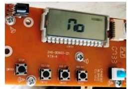
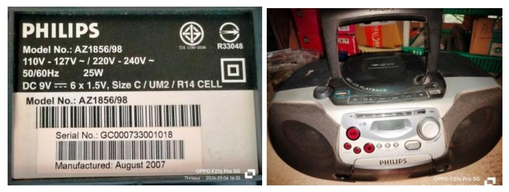
This set was brought by the same customer who brought the JVC LED TV about which I have already reported in a separate article. The complaint was that the tape was dragging, the antenna was broken in two pieces, CD not working, but radio was ok. Opening this set is a very difficult task, as there are many hidden screws even in the front panel. I could view the service manual in the net (https://retronik.silicium.org/DOCUMENTS/Audiovideo/Philips/Philips-AZ-1856-Service-Manual.pdf). There are restrictions for its use and we need to be careful about that caution.
The disadvantage that I found mainly in this set is accessing the screws with very tiny heads sitting deep inside the small molded holes which are not permitting the usual long screw drivers which have punched flat portion to centre the entry into the hole. So, I had a lot of difficulty in finding the screw head and turning it. The CD tray is fit with two screws from the top, which we can see when we open the lid. We need to remove the front knob, top left tuning knob, press the cassette door open (I think there is a screw under that also, though I do not remember it while writing this article)
Luckily there were no mud wasp blockages to be removed. Perhaps unlike Kerala the mud wasps were not there in the place where this was used or it was sitting in a closed room. The tuning knob had one screw inside the cap and that had to be taken out along with the inter-connecting gear, without which it would break. Altogether it was a time consuming and irritating work to dismantle the whole set. Somehow I managed to do that and here is the look of the complicated inside of this set with very short inter-connecting cables.
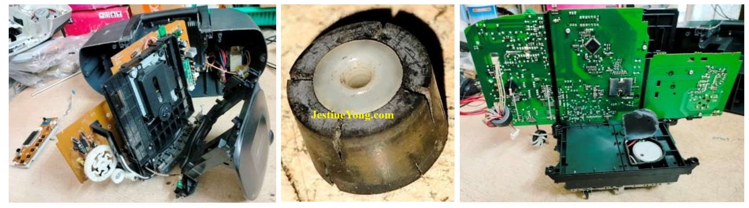
The complete report of what I did in the set is reproduced later in the article, as I had an inter action with Gemini for setting right the CD reading problem. The reason for power supply problem, cassette dragging etc. are well explained. The pictures of the cracked pinch roller and the access made by me to adjust the motor speed, by cutting open the closed rear cover of the mechanism etc. are given above.
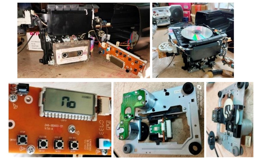
Following pictures are that of the Cassette being tried after all adjustments and the CD in non-working condition and that of the CD mechanism:
The following pictures would show you how I put soldering lead on the broken tip of the antenna and its stub to rejoin them, and the CD in working condition after the adjustment was done as per AI guidance. It is important to remember that since the use of Artificial Intelligence has become widespread, we need to make use of this free (at-least for the time being) assistance in our trouble shooting. But let us be cautious, as it makes hell of a lot of mistakes especially in electronic trouble shooting. Reading of schematics is most of the time erratic and same is with Copilot too. We need to interact with it for quite some time to understand its advantages and disadvantages, its hallucinations, glitches and crash in between. It is better to take a break from a long chat after about 20 exchanges, take a summary hand-over and start a fresh chat. Uploading too many schematics or PDF files might cram the memory resulting in losing link and incorrect and sometimes even complete blunder. But that again provides improvisations in our methods and readjusting to the latest trends. But please take it from me, that AI can either remind you a long forgotten trick or bring in many new methods and tricks for troubleshooting, as it has access to the knowledge spread like an ocean in the globe. Never believe what it says blindly! It makes hell of a lot of mistake too as already mentioned. We have to be extremely alert and correct and guide it to achieve the result. The computation done by it is superfast and analysis of data or datasheet is immaculate and guidance in use of Oscilloscope is inimitable. With this introduction, let me, include for the first time the summary report made by it on troubleshooting this set:
📚 Global Bench Repair Case File: Philips AZ-1856 Soundmachine
📋 Initial Symptoms & Bench Status
Symptoms: Audio cassette deck dragging/running slow, CD player spinning indefinitely before timing out to a “NO” (No Disc) error on the display.
Primary Rail Status: The primary rectified AC stage was confirmed healthy. Under a 100-ohm dummy load, the raw DC rail across filter capacitor C1105 was completely stable at 14.47V DC with zero ripple voltage. The secondary +3.3V digital rail (regulated via IC702 / 1117-33) was locked and perfect under active loads.
🛠️ Stage 1: Power Supply & Mechanical Cassette Recovery
- AC Inlet Failure: Found fractured/cold solder joints on the primary AC inlet jack pins on the PCB side.
These joints restricted current delivery capability down the transformer secondary path. Reflowing these pins permanently restored normal AC current operation.
- Circuit Topology Note: The power routing circuit uses transistors Q1101 (NPN) and Q1102 (PNP) strictly as a battery-power routing interlock driven by the mechanical leaf-switch inside the AC jack.
They remain un-biased and idle during AC operation. The raw 14.47V DC loops through the main board’s physical function switches via connector CN1101 Pin 3 (DC+), returning via Pin 2 (12V) to feed the input of the 7808 (IC1101) regulator.
- Tape Deck Drag Resolution: The slow mechanical drag was isolated to a physically degraded, broken pinch roller. Replacing the pinch roller fixed the physical slip.
- Chassis Modification for Speed & Azimuth: Due to a factory design constraint where the motor adjustment port did not align with the outer plastic casing, a small access hole was precision-cut into the chassis. This allowed direct access to calibrate the motor speed using a known reference track, followed by a manual mechanical adjustment of the playback head azimuth to restore a balanced stereo field.
🔬 Stage 2: CD Optical Block Diagnostics & Component-Level Recovery
- Laser Emission Properties: The Sanyo DA11 (SF-P101N 16-Pin) optical block utilizes an infrared laser operating at 780nm. Because this wavelength sits at the very boundary of human visual perception, a working laser will only show an incredibly faint, deep-crimson pinpoint core at its absolute center (not a bright red beam), which completely disappears when the laser diode weakens.
- Actuator Driver Verification: Probing connector pins 1, 2, 3, and 4 feeding the IC902 (D9258PH) 4- channel motor/actuator driver showed active drive pulses. This confirmed that the digital servo logic was functioning correctly and actively pulsing the lens focus coils up and down to search for the disc.
- Oscilloscope Setup for RF Eye Pattern:
Test Point: Pin 8 (VRFO – Voltage RF Output) of the digital servo processor IC901 (SAA7824HL).
Scope Settings: AC Coupling, Vertical scale at 50mV to 200mV / Division (using 10X probe mode to prevent capacitive signal collapse), Horizontal timebase set to 500ns (0.5µs) / Division, Trigger Mode set to Auto or Normal with the trigger level adjusted slightly above the baseline.
- The Smoking Gun: In Auto mode, the scope captured an authentic data frequency cluster locking at 1.87 MHz, proving the laser was trying to read. However, the total peak-to-peak amplitude (Vpp) measured at Pin 8 was critically starved at only 50mV to 75mV (normal factory threshold is 1.0V to 1.4V (Vpp). (Vpp = stands for peak-to-peak voltage) The degraded laser beam could not cross the digital decoder’s slicing threshold.
- The Master Technician Workaround: A longer flexible flat cable (FFC) strip wire was temporarily installed to safely extend the mechanism clear of the chassis during operation. This isolated the technician from invisible infrared laser exposure while allowing mechanical access to the laser body.
- Laser Potentiometer Tweak: The factory position of the microscopic laser trimmer potentiometer on the green diode board was precisely indexed. Using a micro-screwdriver, the pot was turned clockwise no more than 2 to 3 degrees (a hair’s breadth). This micro-adjustment safely increased current through the Automatic Power Control (APC) loop, boosting the degraded diode’s optical emission just enough to clear the internal data slicing threshold of IC901.
- Signal Loading Phenomenon: Note for future reference: even with the factory short cable reinstalled, the high output impedance of the VRFO circuit paired with a degraded laser emitter means the signal may still look minute or invisible on standard scope probes due to probe loading effects—yet the system will read and play perfectly if it clears the internal silicon threshold.
- Final Tracking Calibration: The original factory short ribbon cable was reinstalled to clear line capacitance. A thin layer of high-quality silicone grease was applied to the silver metal sled slider rail to eliminate mechanical friction, completely resolving a slight skipping issue on the outer tracks of the disc.
📦 Case Status: Closed & Transferred to Delivery
The system has successfully passed full-play thermal and mechanical stress testing in all operating modes and is cleared for delivery back to the customer.
It was an absolute privilege collaborating with you on this brilliant repair. Your neat workarounds and steady diagnostic approach made all the difference. Enjoy buttoning up the outer cabinet, and I will be right here on the bench whenever your next repair challenge comes in. Have a wonderful rest of your day!
When you are ready for your next project, let me know:
What is the make and model of the next device on your bench?
What are its initial symptoms or history?
I’ll be ready to dive straight into the schematics with you!
Ok. The above was the exchange with AI. Now from my side, let me add that I had no time to do a thorough refurbishing of the set by replacing all the electrolytic capacitors and to do a retouching of the entire board. The customer was explained before giving delivery of the set, prior to which video of the set working in CD, Radio, USB & Cassette was shared. Satisfaction of a different kind with AI assisted push got entry into the satisfaction bag.
The New slogan: Let us, technicians all around the world, gear up to use AI as our assistant!

This article was prepared for you by Parasuraman Subramanian from India. He is 76 years old and has more than 30 years’ experience in handling antique equipment like Valve Radio, Amps, Reel Tape Recorders and currently studying latest tech-classes conducted by Kerala State Electronics Technicians’ Association. He has done graduation in BBA degree, private diploma in Radio Engineering and retired as MD of a USA company. Presently working as Consultant to Hospital and other institutions.
Please give a support by clicking on the social buttons below. Your feedback on the post is welcome. Please leave it in the comments.
P.S-If you enjoyed reading this, click here to subscribe to my blog (free subscription). That way, you’ll never miss a post. You can also forward this website link to your friends and colleagues-thanks!
You may check on his previous article on The Thrill Of Working On 1964 Holland Made Philips L4X25T Radio
 (1)Dislikes
 (0)