
A Severe Case Of Surge Voltage Damage In IMPEX LED TV Model GLORIA 32
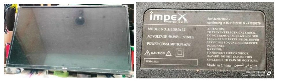
This TV belonged to an employee working in the grocery shop opposite to my house and was brought to me with the complaint that the mains fuse in their house blew on switching on this TV and it was found dead when checked after restoring power in their house. A clear cut case of power failure. I opened the set after my return from the hospital and keeping it on the Verandah of the car porch, used the blower and brushes to clean up the inside thoroughly.
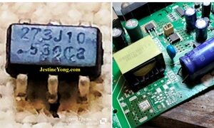
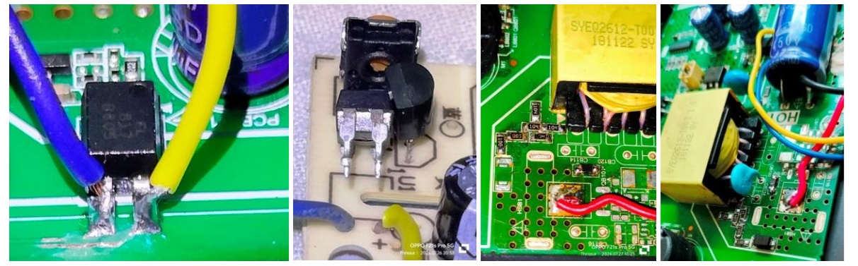
On checking up after bringing the set to my service table, I noticed that the 3.15A fuse was blown. The switching Mosfet was short. A couple of SMD diodes on the 6 PIN switching IC were also short. A 470uF/16V capacitor in the secondary was found bulged. The switching IC would definitely have gone and therefore, I removed all the components in the primary and made it bare. Replaced the bulgy capacitor and another adjacent to it.
Then used my ring tester in the primary winding and found the ringing was healthy with all LEDs glowing. Then applied power and checked the voltage at the tank capacitor, 47uF/500V. I noticed that the voltage was initially building up to 325, but dropping gradually. As there was no load, this is a wrong sign. I replaced this capacitor and then checked and found that the voltage was steady and it remained like that. Let us have a look at the tiny 6 pin IC and another connected image.
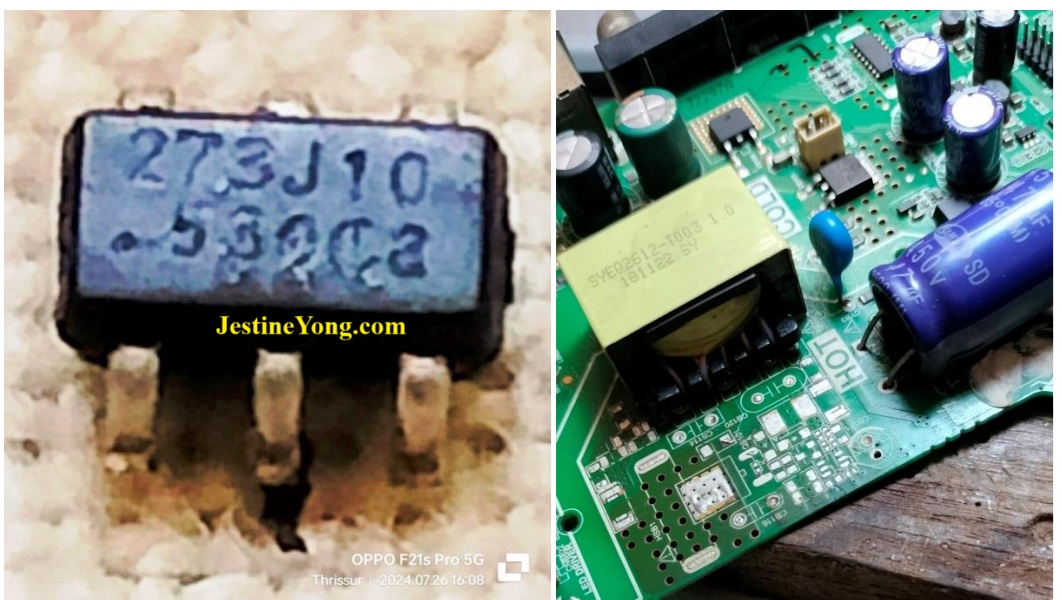
The replacement of the IC was not available and the only option was to provide a 5-24V module or a five wire module. I opted for the 5-24V module because of the recommendations of my techie friends. You will notice from the second picture above, I had removed the oscillation filter circuit from the primary, which consisted of four 104 SMD resistor (100K) and two 10 Ohm resistors, one parallel capacitor, 222K/1KV, and an SMD diode. This was a mistake. This circuit should be there as a protection for the Mosfet and correcting noise. So, I replaced these resistors and the diode later.
The anode of the diode should be connected to the drain of the Mosfet. The two sets of 104 are in parallel, the 10 Ohms were in series. The capacitor had got punctured, so I replaced it with a new one. Then I used a safety trick as suggested by my techie friends: Check that the opto-coupler circuit of the original board is good. If that is ok, cut the pins 3 & 4 in the primary side. Then remove the pin 3 & 4 of the opto in the 5-24 module and remove the blue and yellow wires and directly connect the 3&4 to the TV board. In this way, the secondary voltage will be generated as designed by the TV manufacturer and maintained it that way by the primary of the module. In a way, we can say it is a sort of ‘grafting’, using the best of both. The red wire of the module was connected to the return wire of the SMPS transformer (point where drain was connected), the other end of which is fed the B+. The black wire was soldered to the hot ground.
That’s all! Let us look at some pictures:
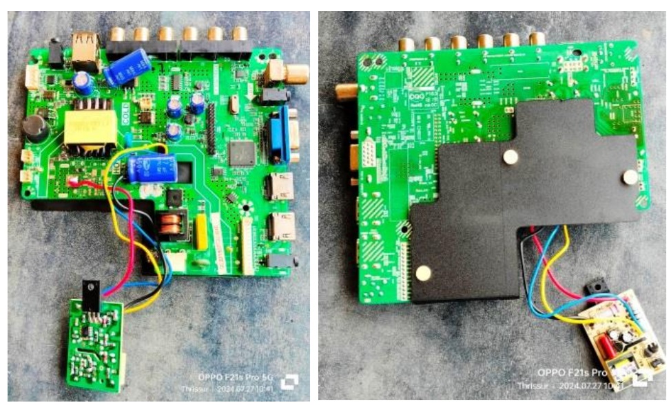
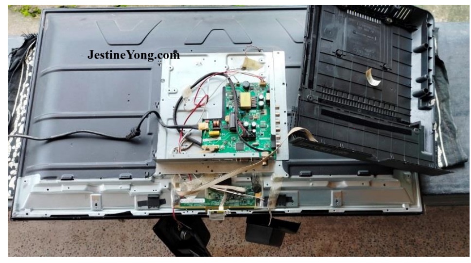
I had tried the working before putting the 104/10Ohm resistors and diode in the primary and it was found working. Hence you might see a few pictures without these components in place. I fixed the module on the LED backlight metal back-cover with a heat sink pad provided underneath. The picture you see below is just to show how it was fixed, as I removed the board again to populate the 104/10Ohm resistors and diodes in the primary.
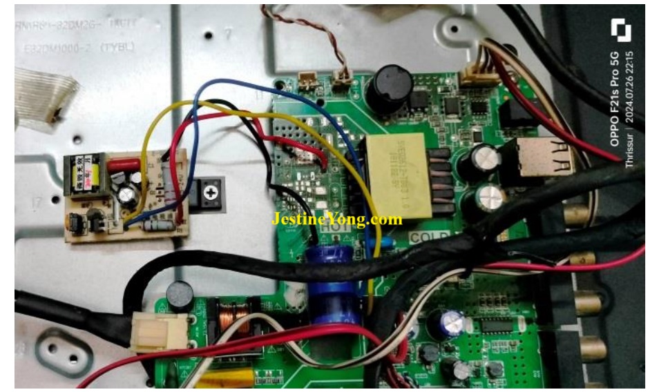
The secondary voltages were 12V and 48V (for the LED driver section). I allowed the TV to run for several hours before putting the back cover and informing the customer to come and pick it up.
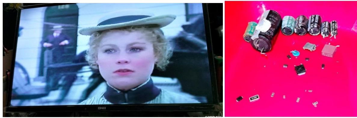
I had also replaced the 100uF/63V cap, 22uF/160V and 470uF/10V and that is why you would find these in the tray above. The SMD components that you see at the bottom are good ones, but I did not want to keep it and gave to the customer along with the defective components.
Great mission accomplished for which purpose, I got up at 3 AM in the morning though I had hit the bed only at 11.30PM in the previous night. Intense satisfaction in the verge of bursting got quickly tucked to the collection bag to avoid another damage! (LOL)
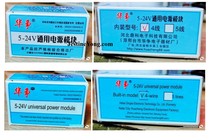
P.S: Some of you have been enquiring about this 5-24 Board. Here are a couple of pictures of the cover, which is in Chinese. I used Translator online and got its English version, which are also given:

This article was prepared for you by Parasuraman Subramanian from India. He is 74 years old and has more than 30 years’ experience in handling antique equipment like Valve Radio, Amps, Reel Tape Recorders and currently studying latest tech-classes conducted by Kerala State Electronics Technicians’ Association. He has done graduation in BBA degree, private diploma in Radio Engineering and retired as MD of a USA company. Presently working as Consultant to Hospital and other institutions.
Please give a support by clicking on the social buttons below. Your feedback on the post is welcome. Please leave it in the comments.
P.S-If you enjoyed reading this, click here to subscribe to my blog (free subscription). That way, you’ll never miss a post. You can also forward this website link to your friends and colleagues-thanks!
You may check on his previous article on E0 Error Solved In ADELI Induction Cooker Model AL-2000A1
 (56)Dislikes
 (0)
(0)
18 Comments
Leave a Reply


Waleed Rishmawi
October 24, 2024 at 11:51 pm
That TV survived the major operation then went through recovery in the ICU LOL. Good job my dear friend you revived it and made it work again. Have a blessed day
Parasuraman S
October 26, 2024 at 9:12 am
Many thanks for your encouragement, dear friend!
YogeshPanchal
October 25, 2024 at 12:07 am
Good job! Sir,
Thanks to the technology NO live chassis now... long back i damaged one SONY CRT TV connecting this type of module & fitted it on the chassis.....
Parasuraman S
October 26, 2024 at 9:14 am
Oh! Our bad experiences actually give us more courage to face new challenges! Many thanks, dear Yogesh Bai!
Albert van Bemmelen
October 25, 2024 at 1:09 am
Thanks for the extra given info with translated into English explanation of the used 5-24 board Parasuraman. Very informative but sadly still all too complex for my taste since I do not even own such a board. Nor did I ever use such a power module in any repair myself successfully either yet. TV repairs like these are simply too risky to handle.
All new made modifications you had to make to fix the issue no doubt will intensify any future repair if this tv revisits you next time.
Parasuraman S
October 26, 2024 at 9:15 am
Many thanks for your analytical expert comments, dear Albert!
Mark J
October 25, 2024 at 2:40 am
Parasuraman good article. Well done on the repair.
Parasuraman S
October 26, 2024 at 9:15 am
Many thanks, dear Mark!
Imoudu.O
October 25, 2024 at 4:30 pm
Thanks for sharing sir,for i have this 4 wire module also,but i never use it.I can see you use it on tv universal combo mother board.
Sir, can it be also used on original tv power board as you described?
Parasuraman S
October 26, 2024 at 9:17 am
Yes, for bypassing work, this is the best, upto a limit of 32 to 40" TVs (Low power consumed). Many thanks, dear Imoudu!
PHILIP
October 25, 2024 at 9:07 pm
I was following closely your every move until cable connections began, the kind of stuff meant for professionals. But I will go through the article so slowy later on and I know I will no longer be scratching my head because clear pictures with abit of knowledge help much. All the same, thanks.
Parasuraman S
October 26, 2024 at 9:17 am
Many thanks, dear Philip!
Hollis LuQuette
October 26, 2024 at 1:07 am
Great work on that repair , I ordered some of those 273J10 chips from Ali Exp ress a couple years ago 10 chips were less than 2 dollars USD .... Ebay and Ali Exp ress still have those for sale ....
Parasuraman S
October 26, 2024 at 9:18 am
Glad to hear, dear! Many thanks for your comments and feedback!
Tito Kanshulu
October 30, 2024 at 5:36 pm
Good and excellent repair article Mr Parasuraman. I can see that the power module was expertly planted. Sometimes these modules have been found to produce a pulse in the output of crt tv. I don't know why. Maybe it's poorly connected, I don't know.
Parasuraman S
October 31, 2024 at 6:41 am
I could not follow exactly what you meant about pulse in the output of CRT TV. If it is some visible lines or wavery forms, it could be caused by bad filter caps. The cap from hot end ground to cold end ground also should be replaced. Many thanks for your comments!
Mahmoud
November 11, 2024 at 5:09 pm
it's a good article ... well done
Mr.Parasuraman
Parasuraman S
January 18, 2025 at 7:58 pm
Many thanks!