
Overboard Servicing Done In AKAI Cassette Deck Model GXC-709D

This Tape Deck was brought by a regular customer with the complaint that it was stopping after a few minutes play. This deck was taken to another technician near his house, as I was overloaded with pending jobs and declined to accept anything further until it came under control. According to the customer, that technician found the original motor defective and replaced it. But it did not solve the problem and he waited until I was free to bring it in. I switched on the deck in front of the customer and played it and found that the tape was wobbling, upon which he told me that he tried to replace the belt, but as a replacement of the same width was not available he cut the size and pasted it. So the lump on the belt was causing this wobbling! Could that be the cause for switch off? Well, I thought so and accepted the work and also checked the work done by the other techie. He had just replaced the motor with a 12V CCW. The customer had brought three motors for selection of a replacement, as the original motor was large and the replacement alredy made was not exact, which the other techie had already cautioned. But those motors were all CW and not CCW.
So I returned them. Another complaint mentioned by him was the rewind was not working. I continued my work on the deck after he left. First and foremost job was to replace the belt, which I could do easily by lifting the capstain wheel fixing bracket from behind, as it was easily accessible. After that I checked the voltage that came to the motor. It was showing around 15.5V! I guessed immediately what was wrong. The original motor might have been a 15V large motor and after replacement the voltge should have been regulated to 12V, which either was overlooked or not done.
Naturally, the motor would get heated up quickly and the thermal cut off in the control circuit inside the motor would trigger. So, I fixed a 7812IC near the motor on the chassis using one of its own fixing screws and wired the ground and in/out provided with 220/25 Electrolytic cap on both sides, which can be seen below:

Then played one cassette full, A & B sides and it was found working very well. Then I replaced the belt on the rewind gear with a round sized belt as I had the original Sony, size of which was exactly suitable. Then the rewind problem was also solved. Let us have a look:

While checking like this, I was wondering why the auto switch off mechanism was not functioning in this deck. I checked and found out that it had a solenoid, plunger of which was connected to the lever that releases the hold of buttons pressed down. But it was not working. I also saw a hall sensor connected to a magnetic wheel, which meant that the solenoid should be activated once the pulse stops from it, as the wheel is linked to the collection wheel of the mechanism. (I forgot to click a snap of this portion to show to those who are not familiar with this type of set up) I checked the pulses when the tape was running and it was getting generated. The Solenoid had the positive potential at both ends, one side of which should be pulled down to ground by a switching transistor to activate the electromagnet to suck in the plunger, which in turn would pull down the lever releasing the switches, which also releases the positive supply to the motor through a leaf switch. As I am accustomed and well versed with these, I am explaining in a flow and I doubt whether those who never handled tape mechanisms could ever follow me! It is also not advisable to use too many pictures in this article, which would burden our Jestine Yong, who is already too busy with tight schedules of his priorities.
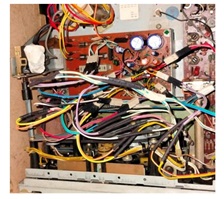
As removing and checking the PS board which housed the control circuit was almost impossible practically due to several wires wound on legs very closely that hampered tilting of the board for a check-up, I sent a message to the customer and enquired whether the auto stop was working and should I attend to it too, which did not get a response until very late evening, by the time of which, I had already closed the set after conducting thorough tests and moved it to the delivery point. (Unfortunately, there were no connectors and all wires were directly connected to one another in the entire board.) But his response that it indeed was working and he was surprised to hear that it was not working, put me in a jam! I had then the moral responsibility to look into that problem for which I reopened the set and sent him a video of the inside wiring and the complexity of the same board handling the 230V AC input too, for which the wires were connected at the other end from the transformers. Though I managed to remove the transformer and kept it on top of the mechanism and managed a tilt of the PCB, no checking was possible at this angle, especially when the 230V AC input was present at one end! Just a have look:

I told him that I wanted to remove all the various AC inputs such as 120V, 140V etc. and connect the input to the transformer directly from the mains to the 240V AC instead of the 220V AC input which it was connected to. He agreed and then I removed all the AC input wires from the board. Then cut the ends and securely taped the unused wires on to the transformer. Then provided a fuse at the AC input, which the set was not having (Surprised?) and fixed the transformer back in its place and isolated the AC input portion securely tying it up to the rear cover of the set. Then trimmed the secondary wires, provided crimps and inserted into a Relimate housing connector. Let us have a look:

Then cut all the wires leaving sufficient margin on the PCB side to provide crimps at the wire ends once again to use Relimate housing connectors. Let us have look at the female crimps and housings stocked by me for such odd uses:

Then crimped the wires (there were around 22 wires that were coming out of the PS PCB) All these wires were wound on legs provided for the purpose. Let us have a look at the PS Board before and after the work:

Then took five inter connecting wires which had male headers on both ends. Then crimped one end to a .1” female crimp and inserted that side on the secondary AC input legs. These were fitting very tightly indeed. Then inserted the other ends in the same order to the connector which I had made for the AC transformer. Let us have a look at the pictures. The inter-connecting wires are shown in the second picture (These are readily available in the market)

You can see the female crimps holding on to the legs tightly in the third picture above. It was almost equivalent to the wire wound set up! The orange wire was for 31.V for the solenoid, Grey was for 7V for the lamp, two yellow wires were for the 15V and the red wire was the starting point of the secondary winding. Let us have a look at the circuit diagram of the Power Supply Board to follow the connections for an easy understanding (Please use control and upward arrow to zoom):

I forgot to mention that after cutting the wires, I checked the ESR and values of all electrolytic caps in the PS board and found these to be abnormal, a couple of readings of which are given below:

As you can perhaps read, the 2200uF was reading as 2612uF with an ESR of 16 Ohms and 330uF was reading as 397.8uF with an ESR of .32 Ohms. After replacing all the e-Caps, I retouched the board thoroughly.
Having ensured that the PS board was ready to take the load, I turned my attention to the cut wires left on the set.
Then crimped the ends with .1” female connectors for inserting inter-connecting wires like how I did for the secondary AC connection from the transformer. Let us have a look at the pictures of, before crimping and after crimping:

Then removed the outer casing at one end of the inter connecting wires to enable easy and deep insertion into the .1” female sockets that I had crimped to the wires of the mechanism and other board sides, which you see in the third picture above. Then inserted that exposed male pin into the female sockets of the wires with as much matching of colours as possible. The connection was so firm and superb and I felt as though the bonding was better than soldering!

In the picture above, you could also perhaps see that I had inserted a small length of heat shrink sleeve to cover the joints. After finishing that, the next step was to connect the other end of the wires to the appropriate connectors in the PS board, which was very crucial and required rapt attention, focus, concentration and precision. I started the insertions from one end of the PS Board, checking and rechecking and pressing the male and female connectors tightly to ensure that there were no loose contacts. This took a hell of a lot of time and I felt strain in my eyes as well as brain.
I did take rest in between to play chess game in the computer to come out of weariness. Let us now have a look at the finished work:

Left it without checking for the night and rechecked all connections in the next day very early in the morning. Then marked each connector after ensuring that the wires to the PS board were going to the appropriate points. Luckily, the wires had different colours and stripes for easy identification and I had to only follow the colour of the inter-connecting wires that I used. After this final check, which was similar to what they do in a rocket launching station, before a launch, I ventured enough courage to power the set and see what happened. To my extreme happiness, the set worked very well with auto stop and all other functions and the audio output was also much better as the Power Supply was stabilized. I played cassettes for many hours and it worked flawlessly, which brought a great relief to me. I was taking care to post pictures and videos to the customer to keep him apprised of what was happening to his favourite set. Can I say now that mission got accomplished and great satisfaction with sweat of toils and boils got sucked by the collection Bag? Now, do you all agree why I captioned this article as ‘Overboard’ ?
Sometimes I feel that I am overdoing certain things and many of my techie friends have asked me whether I was insane!
Well, I don’t blame them! Mine is an electronic insanity and I love to have it! Ha! Ha!

P.S. Why two fuses in the picture? One was directly shorted by a previous techie and I replaced it with the correct value and the next one (800mA) blew when I was testing because of the 7812 IC that I had connected in the motor section.
Perhaps it would have drawn additional current. I replaced it with a 1A. Both these fuses were in the secondary.

This article was prepared for you by Parasuraman Subramanian from India. He is 74 years old and has more than 30 years’ experience in handling antique equipment like Valve Radio, Amps, Reel Tape Recorders and currently studying latest tech-classes conducted by Kerala State Electronics Technicians’ Association. He has done graduation in BBA degree, private diploma in Radio Engineering and retired as MD of a USA company. Presently working as Consultant to Hospital and other institutions.
Please give a support by clicking on the social buttons below. Your feedback on the post is welcome. Please leave it in the comments.
P.S-If you enjoyed reading this, click here to subscribe to my blog (free subscription). That way, you’ll never miss a post. You can also forward this website link to your friends and colleagues-thanks!
You may check on his previous article on Failed Cases Of Two SONY LED TVs.
 (31)Dislikes
 (0)
(0)
14 Comments
Leave a Reply


Albert van Bemmelen
October 4, 2025 at 7:07 pm
Excellent repair as always dear Parasuraman! It still is a mystery to me why the auto stop didn't work anymore and how you manage to fix it?
About the provided fuse at the AC input, which the set did not have... could it be that the transformer coil internally still had a thermal safety fuse?
Parasuraman S
October 4, 2025 at 11:22 pm
1) The change of caps as well as fresh solderings would have cleared the hitches, as current flow was restored for proper functioning of the solenoid.
2) This transformer do not have a thermal fuse built in unlike the Philips and many other transformers that we find.
Many thanks for your expert comments and encouragement, dear Albert!
Mark J
October 5, 2025 at 2:43 am
Parasuraman I like your electronic insanity. It shows that you are dedicated to getting the repair done and seeing it through. Thank you for sharing.
Parasuraman S
October 5, 2025 at 11:11 am
Many, many thanks, dear Mark!
Philip
October 5, 2025 at 2:41 pm
You were all over the board solely with a fixed mind to repair it. Insanity is when some technician disolders a handful of the crisscrossing cables and leaves them hanging, or indulges on a questionable exercise of pulling out unknown ICs. Without a similar board or a schematic to refer to for ideas, that will leave most of us techs stuck; no trial and error, no guess work, no risking, no nothing ! End of story !
Parasuraman S
October 6, 2025 at 8:31 am
Yes, tampering is a nightmare for technicians who want to do a thorough repair job. But with the schematic, most of it can be restored. Right now, I am working on a three-in-one Sharp set, radio board of which has been very badly tampered. Hours, days and weeks have already passed on it! But such challenges keep us charged and pushe us further and farther. Many thanks for your comments!
Philip
October 5, 2025 at 6:48 pm
Unlike the usual SMPS circuits, I'm tradeing on an unfamiliar ground here. The enlarging isnt very clear, but what little I can make of the power input of the circuit is that power goes directly to what I perceive to be an input transformer then through fuses, then to the rectifier packs ...... to me it looks like a good arrangement from the surge protection perspective. The transformer and the fuse and diodes absorb the whacking during a wrecking invasion.
Parasuraman S
October 6, 2025 at 8:35 am
Yes, the AC input is to a step down transformer from which secondary voltages are tapped. Though the transformer would stand and protech such surges, the primary would get burnt as there was no fuse and not even a thermal fuse! Many thanks for your involved comments, dear Philip!
George Persico
October 6, 2025 at 12:55 am
Very nice VERY well documented repair, pictures tell the story.
Parasuraman S
October 6, 2025 at 3:40 pm
Many thanks for your encouraging comments!
Waleed Rishmawi
October 7, 2025 at 1:54 pm
a very detailed and lots of information provided...I got distracted along the way but I finally got it...thanks for sharing and what you did is amazing...keep up the good work and have a blessed day
Parasuraman S
October 8, 2025 at 8:34 am
Many thanks, dear friend! May God bless you too!
Yogesh Panchal
October 8, 2025 at 8:41 pm
Excellent Repair! Sir,
The company should have used a PCB holder connector instead of a bunch of jumpers.
Parasuraman S
October 9, 2025 at 3:46 pm
Yes, very true! Many thanks for your comments, dear Yogesh Bai!