
Samsung LCD TV LE37R86BD Picture Quality Problem Repaired

This Samsung LCD screen TV set belongs to Marios, a close friend of mine. Last time I visited him he complained that the set reproduces the pictures with very bad quality. Here is his description:
“If you see the peoples’ faces, they look like zombies. There is something like black tear-drops in the edges of their eyes and similarly at their mouths. There are as well many white lines all around the picture and some times various surfaces look like being aluminized. I also see ghost-imaging, especially related to titles of previous scenes which do not disappear easily”…
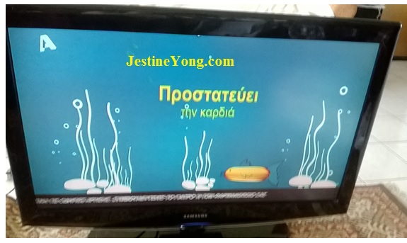
The set’s front view is shown below.
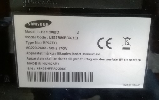
The model number is that shown below.
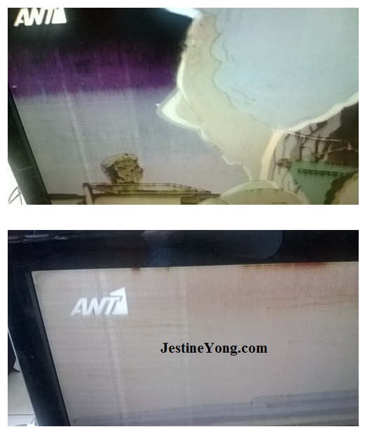
As I put it in operation, in the beginning everything was normal. No problem at all. And this lasted around half an hour. Then, little by little the symptoms that Mario described to me started to appear…The picture became as shown below…
Marios asked me to take it with me and try to repair it and this what I did. First of all, before starting to troubleshoot it later on, I searched in the web to find any relevant information for this specific model, but I didn’t find anything. Then I decided to open it and troubleshoot it. After removing a thousand (!) screws of the back side, I finally saw its electronics. First I tried the “heat it-freeze it” method while seeing the problem on screen. No fruitful result whatsoever…
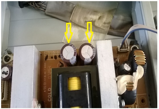
The “finger-as-thermometer” test did not reveal anything further. All I.Cs were operating normally, with no fever symptoms! Meanwhile I noticed that two electrolytic caps in the power supply section were bulged. I turned the power off and then I “scanned” it all around for high ESR caps, apart from those two. I spotted another one, an SMD type on the main board, which was marginal in ESR value and decided to replace them all. Below you can see the two 1000uF/35V caps already replaced, just above the transformer.
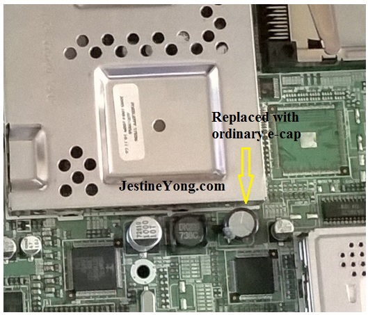
And here below you can see a part of the main board with two electrolytic caps, one at the left side and one at the right side of the smoothing coil, just below the big shielded area. I replaced the original (at the right side of the coil) which was the same type as the one at the left of the coil, with an ordinary one (non SMD type). Its rating was 1000uF/10V.
Then, I powered the unit again hope that I had eliminated all the problems of this set, but I was unlucky. The problem was still there… I thought to continue with the “heat it – freeze it” method at a time before the appearance of the problem. I tried it in the circuits of the main board with no positive results.
Next, I removed the shield of the T-Con board and tried to clean the contacts of the ribbon stripped conductors connecting this PCB with the display, because they were rusty enough. After the cleaning the two multi-pin connectors with cleaner spray and using a soft tooth-brush, the picture was improved but the problem was still present, appearing after some minutes of operation.
Then I tried the same method on this board as well, while the picture was good. Well, as soon as I sprayed on the tiny AS 15 – AF I.C the picture became almost negative. I repeated the same test several times just to be sure that there was problem with this set. After confirming this, I called the official service department here in Athens, to ask them about the availability and cost of either the defective chip or the T-Con board. The answer was negative for both of them.
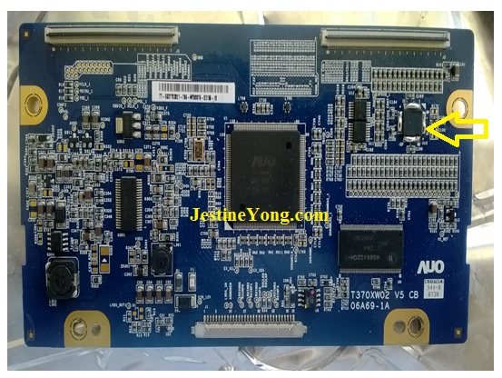
After that I tried to find this I.C in the domestic market. No result either… I searched the web and found (through e-bay) a supplier from Hong Kong and ordered some pieces. When I received the chips, I removed the T-Con board from the chassis in order to replace the defective I.C. It’s the one surrounded with solder in all over its pins, as shown below.
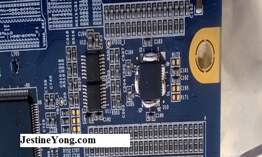
 Below is a part of same PCB showing the area of interest.
Well, I tried very hardly to remove this chip using the methods I know so far, with no result. It was so hardly glued in its back side to the PCB that caused me big trouble. The classic method of heating all the pins with solder overflow on them and the soldering iron tip moving around them until the chip is lifted from its place, failed completely. The feeling I had was really frustrating.
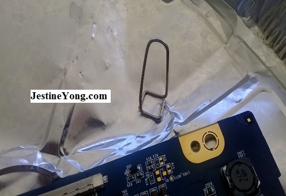
Then I tried a method I saw in the “you tube”, heating the pins with the aid of that jig made from paper-clip and removing the chip by melting the solder and twisting the jig. You can see the jig below, but nevertheless this method failed as well. No result al all.
Having myself been now stagnant from any other brilliant ideas, I decided to cut off all the IC’s pins using a sharp cutter. Finally this was the only effective method to remove it and still, with all its pins cut, this IC was so hardly glued that I used (gently) a small screw driver in order to lift it!
After its removal and the following removal of its pins from their respective pads using the soldering iron tip, I saw four pads lifted. I used a magnifier lens to see some details on the PCB. Fortunately three of them were “blind” (not used) connections and only one had to be connected to the circuit. Now I was forced to run a “beeper”- continuity test to find the connecting point of the other end of the broken copper foil trace. After finding it, I bypassed it with a cable bridge and reinstalled the board on the chassis.
The critical moment had already come…I powered the unit…and you can see the result below.
Below you can see the defective chip (or rather what’s left from it)!
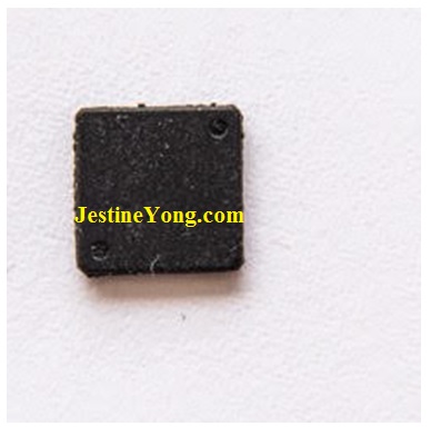
The proper function of the set was restored!

This article was prepared for you by Paris Azis from Athens-Greece. He is 59 years old and has more than 30 years’ experience in electronics repairs, both in consumer and industrial electronics. He started as a hobbyist at the age of 12 years and ended his professional carrier as a senior electronics technician. He has been a specialist in the entire range of consumer electronics repairs (: valve radio and BW TV receivers, transistorized color CRT TV, audio amps, reel and cassette tape recorders, telephone answering and telefax devices, electric irons, MW cooking devices e.t.c) working in his early stages at the official service departments of National-Panasonic first and JVC afterwards, at their premises in Athens.
Then he joined the telecoms industry, working for 20 years as field supporting technician in the sector of DMRs (: Digital Microwave Radio transmission stations), ending his carrier with this subject. Now he is a hobbyist again!
Please give a support by clicking on the social buttons below. Your feedback on the post is welcome. Please leave it in the comments.
P.S- If you enjoyed reading this, click here to subscribe to my blog (free subscription). That way, you’ll never miss a post. You can also forward this website link to your friends and colleagues-thanks!
If you want to learn how to repair LCD/LED TV do check out the links below:
https://www.jestineyong.com/repairing-guides-by-kent/
https://www.jestineyong.com/repairing-guides-by-damon-morrow/
and
http://www.electronicrepairguide.com/lcd-television-repair-ebook.html
 (238)Dislikes
 (2)
(2)
63 Comments
Leave a Reply


Ken
May 12, 2015 at 9:03 am
Jestine,
I've been receiving your articles for about a year now. I just want to say thank you. It's amazing to read these case reports from all over the world. You're doing a great job. I'm so tired of all the other internet repairs involving "bulged capacitors". I think we can move past that!
Jestine Yong
May 12, 2015 at 9:36 am
Hi Ken,
You are welcome and thanks also for all the experts here that had contributed their hardwork.
Jestine
ZARBAN
April 2, 2017 at 12:04 pm
DUMP Orion T32-DLED HK-T.SP9202P63
LSC320AN04-12V
T-con:C320AN02S4
Gary Gemmell
May 12, 2015 at 9:23 am
Nice work Paris i always enjoy reading your fixes - all very ingenious and interesting.
Keep up the good work.
I shall be visiting Greece on holiday this year.
See you soon.
lol
Gary
Paris Azis
May 12, 2015 at 5:16 pm
Hi Garry,
Thanks alot for your positive comment.
I would be happy to see you here!
Regards
Robert Calk
May 12, 2015 at 9:24 am
Nice job, Paris. Thanks for the article.
Paris Azis
May 12, 2015 at 5:19 pm
Hi Robert,
Thank you too.
Greetings!
chip
May 12, 2015 at 9:37 am
Wow.....that was a long process.!
You did a REALLY good job of sticking with it, and figuring out what was wrong.
It is amazing what you can find by chop-sticking, hot/cold/ tapping, etc etc.
Those "low tech" techniques can find a lot of problems.
Well Done 🙂
Paris Azis
May 12, 2015 at 6:03 pm
Hi Chip,
Please try to keep in mind that "big troubles have funny causes". This will help you out not only about electronics' repairs, but in your life as well.
We start from the easier to identify and progressively reach the hardest. Unfortunately there are no shortcuts to this or if one tries to apply any, the results are usually catastrophic.
What I have learned after the years, is that electronics is the synonym of patience.
Regards
Imraz
May 12, 2015 at 11:09 am
Great job without any modern technics used. I use hot air gun to do those kind of repairs but will try your challenging method someday also and see how it goes??
Thanks for sharing
Paris Azis
May 12, 2015 at 4:34 pm
Hi Imraz,
Thanks for your good words. Without any tendency to reject modern or be it more elaborated methods which I fully accept, I strongly believe that "the classic one is irreplaceable".
Regards
beh
May 12, 2015 at 1:20 pm
HI Paris
Thank you so much of this very realistic repair report
indeed all of us as repairer are facing with such problems
like very very strong glued component or even riveted competent
to PCB s . please tell me how much this repair consumed the money
plus your order of this ic from HKG and postage and shipments and so and so
beh
Paris Azis
May 12, 2015 at 4:24 pm
Hi Beh,
The total time I spent including diagnosis and IC removal, was approximately 1,5 hours, but 90% of it was spent for that removal. The worse than anything else was the waiting time for the spare part to come. This counted around 45 days. Practically it was lost and there was intervention of e-bay to spot it. The cost was 11 euros for 10 pieces without any shipment costs.
I have spares for 9 more cases like this one!!
Regards
beh
May 13, 2015 at 1:53 am
Hi Paris
thank you for reply . but have you talked to the SAM SERVICE REPAIR CENTER (SAMSUNG) and asked them for repair or part ? if you did what they told you ? and if not why ? in these kind of problems the service center is another option.
regards
beh
Paris Azis
May 13, 2015 at 4:18 pm
Hi Beh,
This was my first step before starting the repair. Their answer was really disappointing. They claimed that this model was already very old and therefore they don't support it any longer...
This is a seven years old model as they informed me.
Regards
beh
May 13, 2015 at 10:56 pm
Hi Paris
yes same answer are giving to me here if i request repair for a lcd tv like yours .i think this is a world wide policy of Samsung.
by the way recently i wrote an article more or less like your case
and is published in this web log and i invite you to read this one
http://fillwithgoodthings.blogspot.com
thanks
beh
beh
May 14, 2015 at 12:10 pm
Paris
since the tracks of circuit also is going underneath of ics on pcbs
your mentioned Technic,tip of screw driver for lifting up the ics will destroy the tracks and will make the board irreparable.
we have to find a solvent for this glue . thiner does not work. i tested
thanks
beh
Paris Azis
May 15, 2015 at 5:10 am
Hi Beh,
I believe that the designers of this PCB have not been fallen in such a mistake as to glue this IC so hardly with almost no chance to replace it in case that this is needed. Apart from that, under the circumstances I faced with this case as regards the marketing policy behind it, perhaps there is not any interest on their side for any possible repair of it and therefore any relevant provision at the stage of design in order for it to avert any possible damage during an attempt of a technician to repair it.
If this is the real case, I would be happy anyway if there was availability of a spare part at the level of the T-Con PCB for another 5 years time at least, but...
Paris Azis
May 15, 2015 at 3:58 am
Hi Beh,
Of course I'll read your article. About this topic, I also think that their policy is as you say. I think that the supporting time of the official service nowadays seems to be limited to 5 years. After that...
Regards
Abhishek
May 12, 2015 at 3:50 pm
Great work, Great Observation.Good repair activity at ground level to resolve the issue.
Paris Azis
May 12, 2015 at 5:35 pm
Hi Abhisek,
Ground level offers such a safety the other levels cannot offer. Just like in multiple floor buildings while being in danger. You escape sooner!
Regards
Gerald Millward
May 12, 2015 at 4:05 pm
Hi Paris
Very interesting exercise! I strongly recommend a hot-air rework station for replacing large chips. I purchased an Atten 858D+ for a low price from eBay and find it very easy to use for chip removal, particularly where the chip base is soldered to the motherboard as a heat sink. In addition, I use solder paste with the air gun to solder the new chip in place easily and reliably.
Paris Azis
May 12, 2015 at 5:40 pm
Hi Gerard,
I will check this model out to see its performance.
Thanks alot for your comment
Regards
Chris
May 12, 2015 at 4:10 pm
Nice work Paris.
My best regard.
Paris Azis
May 12, 2015 at 5:43 pm
Hi Chris,
Thanks for your comment.
Regards
Anthony
May 12, 2015 at 5:42 pm
Great job Paris ! Thanks for sharing your experience.
Paris Azis
May 12, 2015 at 6:34 pm
Hi Anthony,
My thanks to you as well.
Regards
Capt36
May 12, 2015 at 7:26 pm
I am very impressed at your determination to fix this TV!
I think you educated many of us, concerning troublesome components!
Keep up the excellent article writing!
Paris Azis
May 12, 2015 at 9:56 pm
Hi Capt36,
Thanks for your supporting comment.
Regards
amin
May 12, 2015 at 8:29 pm
Hi Jestine
I'm really happy that you send me your article . im Electronic Master of Science i IRAN and my job is repairing too. so when i see some one in world do this job im really get happy.
thanks Amin
Jestine Yong
May 13, 2015 at 7:16 am
Hi Amin,
You are welcome and I also have to thank to those who contribute those good articles so that the readers enjoy it.
Jestine
Mark
May 12, 2015 at 8:32 pm
Hey Paris,
Well done on the diagnosis! I am struggling with a LCD at the moment. I have tried quite a few methods, but I guess the best diagnostic method is lots of patience!
Paris Azis
May 12, 2015 at 9:37 pm
Hi Mark,
Never give up. Use your brain to establish a logically articulated sequence of steps and apply them one after the other. No rush, no step skipping and you will prevail. Just keep all above in mind.
Thanks for the comment.
Regards
Francesco Cacciatore
May 12, 2015 at 8:45 pm
Nice work Paris, is encouraging to test all the parts to find the problem.
I have a question, when you replaced the SMS Capacitor to the electrolytic one, did the place have holes for the legs, or did you made some artesanal work on it? I'm very courious about that.
Congrats,
Paris Azis
May 12, 2015 at 9:52 pm
Hi Francesco,
First of all thank you too. As regards your question, I merely soldered the ordinary cap on the pads where the SMD one was soldered. There are no holes in the places where SMDs are, but only copper pads to support the relevant part.
Therefore no modifications on the PCB took place.
Note as well that I didn't check all the components of the PCBs, but only the electrolytic caps.
Regards
mark rauch
May 12, 2015 at 9:01 pm
Paris, your determination and tenacity is an inspiration to us all. Many technicians would give up on the TV as not repairable. Your community is blessed to have a technician like you.
mark
Paris Azis
May 12, 2015 at 10:18 pm
Hi Mark,
What an encouraging appraisal! Thanks alot. Well, I am not anything supernatural. I am only an ordinary technician, perhaps with more experience due to my age first and the good fortune of having been cooperating with famous companies along my career, which worked as schools for me in my entire professional path.
As I said elsewhere in this blog ( and Jestine put already a "like" on it) "if you like it, you will conquer it". And I mean the art of electronic repairs.
Greetings
Humphrey Kimathi
May 12, 2015 at 10:01 pm
Excellent Job Paris, i have learn something new.
Regards Humphrey
Paris Azis
May 12, 2015 at 10:24 pm
Hi Humphrey,
The same holds true for me when I read your articles.
Thank you for your supporting comment.
Best Regards
Humberto
May 12, 2015 at 11:12 pm
Good repair Paris, you really avoided an electronic equipment was in the dump at this moment. Congratulations, keep up your hardwork and share your experiences
Paris Azis
May 13, 2015 at 4:25 pm
Hi Humberto,
Thank you for your supporting comment.
Greetings!
sam montero
May 13, 2015 at 4:13 pm
I commend you for great focus in finding the problem and getting a solution. Nowadays lcd tvs are cheaper and owners of defective units
would rather scrap than pay the labor and parts. However, keep up the good work.We learn a lot from you.
Sam
Paris Azis
May 14, 2015 at 5:21 am
Hi Sam,
Thanks for your supporting comment. I know what happens nowadays and I am very unhappy with it.
Repairs is already a dead profession in my country but still I wonder what professions will survive in this ever changing world and for how long. This is the question our children usually ask...
Regards
malik
May 13, 2015 at 8:55 pm
hi s.r
i have a samsung plsma tv model ps43d450
is problem half up screen horizontal lines show
replace y scene borde same problem
plaece help me
thanks for all friend
you
Paris Azis
May 14, 2015 at 6:10 pm
Hi Malik,
I feel that you are inexperienced in repairs. If so, trust an expert to solve your problem. If you insist on working alone, then my single advice to you is this: Find a good friend of yours who happens to have the same model with the one you own. Then, always without powering the unit, replace the boards one by one and test the results after each replacement, until you find the defective one. Then buy a new board and that's all. Unfortunately I don't have a solution of the kind "replace this or that and you are done".
l hope this works for you.
Robert Calk
May 15, 2015 at 1:44 am
I agree with Paris. Plus you don't give enough information. You don't describe the color and look of the lines, and you don't say anything about the OSD or anything.
What experience do you have? Do you have an Isolation transformer?
We don't want to tell someone," Do this and that", and then they get hurt, or even killed.
Yogesh Panchal
May 14, 2015 at 3:10 pm
Excellent tips sir plese do keep sharing your experiance.
Paris Azis
May 15, 2015 at 5:14 am
Hi Yogesh,
Thanks for your support.
Regards
Calin
May 14, 2015 at 8:04 pm
Hi Paris,
Well done but please tell me what kind of methode is “heat it – freeze it” ?
Paris Azis
May 15, 2015 at 5:28 am
Hi Calin,
The "het-it" part means "use a hair dryer and heat the suspect component". On the contrary the "freeze-it" part means "spray it with freezing spray".
It's a common method any technician uses to locate unhealthy components and "non typical failures" like cold solder joints.
I guess you are a newcomer in the repairs field. Keep on learning then! And if you ever intend to apply this method, remember its limits, that is, don't toast any chip trying to test it.
Thank you for your good words.
Regards
reza
May 15, 2015 at 11:28 pm
hello mr Paris Azis
thank u for share this good article.
Paris Azis
May 17, 2015 at 2:07 am
Hi Reza,
Thank you too for your support.
Regards
Antonio Marques
May 16, 2015 at 1:31 am
Dear Paris Azis.
I really enjoyed your detailed article.
Your description to get some results was excellent.
My congratulations and please accept my greetings from Portugal.
Paris Azis
May 17, 2015 at 2:21 am
Hello Antonio,
Thank you too for your warm and supporting comment.
Both your greetings and congratulations from Portugal are fully accepted! Nice country. I have been there once in the past, along with all my family, for tourism...
Best Regards
Mohammed Kasim
May 19, 2015 at 12:26 pm
I enjoyed your valuable article. When will you make a post about OPAMP test gig for measuring small voltage drops for finding short circuit. I am expecting it shortly from you?.
All the best
Paris Azis
May 29, 2015 at 3:04 am
Hello Mohammed,
I didn't forget it and still working on it. (I want this article as better as it can be). Just wait (please).
Regards
Lee
May 19, 2015 at 10:24 pm
Very Good Paris!
I also had a 42" Toshiba TV with exact issue of AS-15 Gamma Correction IC being the culprit of ghosting/negative images. Had to use heat blower to remove it.
Thanks Paris and keep up the good work!
Thanks Jestine for sending us these blogs!
Paris Azis
May 29, 2015 at 3:05 am
Hi Lee,
Thank you for your supporting comment.
Regards
shahid ahmad
May 27, 2015 at 11:34 pm
nice
Paris Azis
May 29, 2015 at 3:07 am
Thank you Shahid.
Corriete
July 12, 2015 at 12:16 am
o yes great job. Sometimes when so hard to find we have to be patient. you did it. but may i ask what did you use to spray the ic? thanks
Corriete
July 12, 2015 at 12:18 am
follow up question. what substance was used to spray the ic and how long did u use the spray for before finding the fault?thanks
Paris Azis
July 18, 2015 at 3:19 am
Hello Corriete,
Sorry for the long delay to answer you. I apologize. I don't remember for the time being the substance you are asking me for, but nevertheless the freezing spray you can find it in stores that sell electronic components. It is a very common material used in our work. Its use is also very simple. Spray the suspected area just like spray painting and then wait for the result. If there is a change from the previous condition, then you have spotted a problem in the area.
Best Regards