
The Thrill Of Restoring Another Lovely Valve (Tube) Radio – Murphy Model Tao-824
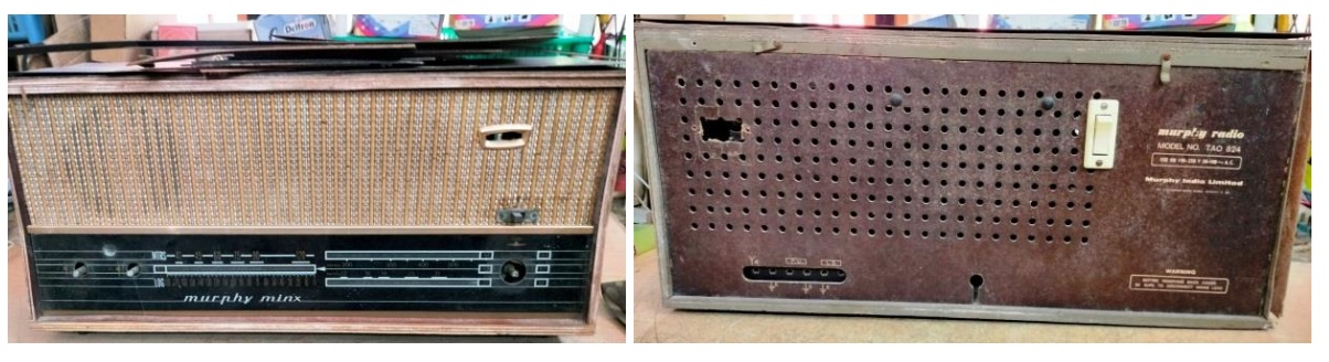
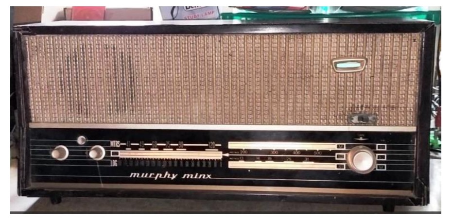
This Radio was brought by a friend of mine and was lying in my attic for many years. The idea was to bring it back to working condition and sell it. The condition of the Radio when it was brought in November, 2016 can be seen in the following pictures:
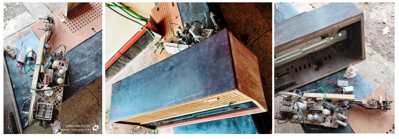
I used to pick it up for showing to prospective buyers and a couple of snaps you see are from such occasions. I decided not to revive it unless someone really comes forward to take it after complete restorations bearing the cost. Finally, there was one who came forward and I took it up for reworking in February, 2025; a patient wait for MORE THAN EIGHT GOOD YEARS! After doing a general cleaning work to the extent possible on a totally battered set, I applied power to see whether something was working, though one valve was missing. The filament of the valves and dial lamp glowed.
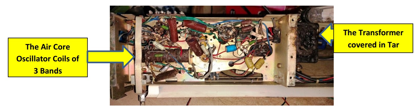
Incidentally, this is an AC/DC set using ‘U’ series of tubes, which are directly connected to the mains, because of which the chassis would be alive! We need to use a tester and if we find it alive, we should invert the two pin plug so that only neutral comes to the chassis. The filament voltages for each valve would be different in U series, because of which the total voltage requirement is arrived and an adjustable variable wire-wound resistor is generally used. But in this set, there was a transformer handling only the filament and dial lamp requirements. Let us have a look:
I saw cracked resistors and fixed capacitors and I went ahead and replaced every one of them first. The cone paper of the speaker was fully moth eaten. But coil was ok. I gave the speaker for replacement of the cone paper and got it back by same day evening.
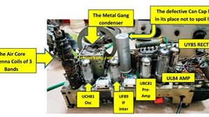
Removed each and every valve, cleaned the legs with metal brush. Lubricated the valve bases and inserted the valves in/out a few times to remove residual dirt and fungi. Applied power. I replaced UY85 rectifier valve as it was arcing.
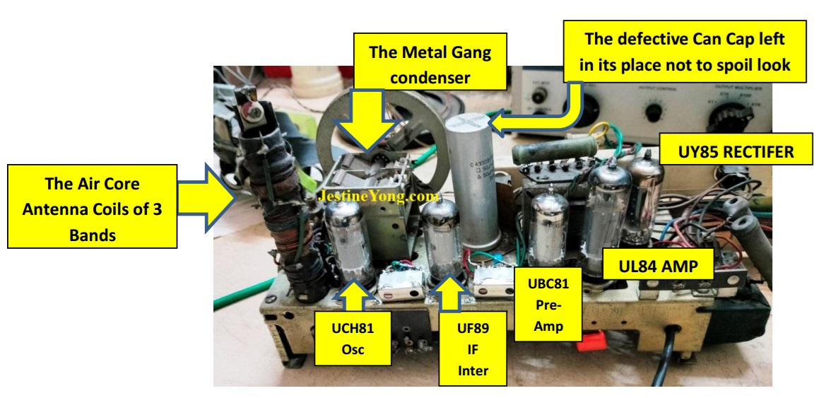
The filter cap had dried out. But allowed it to be there not to spoil the antique look. I connected one 47uF/450V in parallel to 3.3uF/450V to match the 50uF/350V can cap used. Two sets were used to provide filter on first B+ in and after the dropping resistor for IF sections. The can cap was 50uF+50uF/350V. The UBC81 was also arcing and I replaced that too, upon which the amplifier section worked very well. The pots were also lubricated and cleaned well. The tuning spindle and other cord guiding wheels as well as the gang wheel were lubricated for smooth turning. We have to take care not to spill the lubricant on the cord. Otherwise it would slip. This Radio had two needles as the MW bands and SW band markings on the dial were in straight lines and not one under the other as we could see in other Radios.
The valve IFTs were open and could not be used. So, I used two imported IFTs with due modifications, about which I have already covered a detailed report in my article, link of which is given below:
https://jestineyong.com/replaced-ift-with-imported-in-philips-valve-tube-radio-model-major/
This time what I did was directly soldering the wires to the pins after the necessary modifications done. Let us have a look:
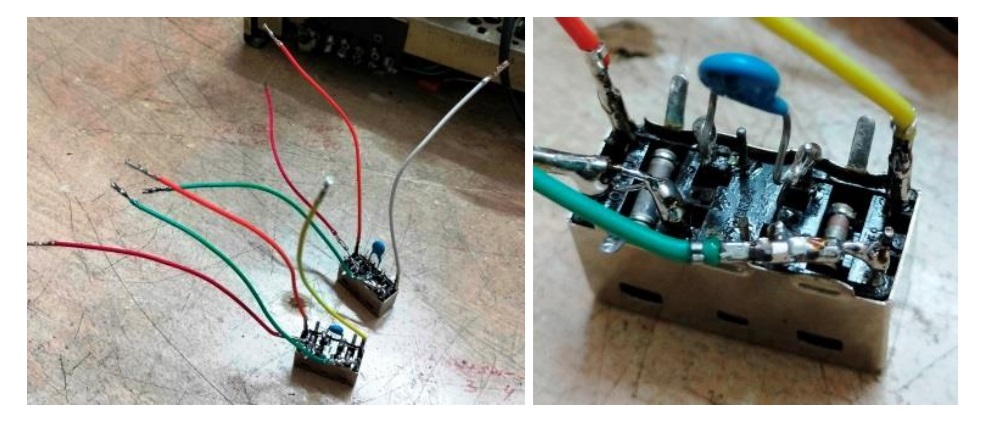
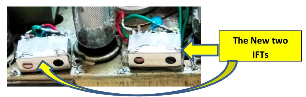
Then fixed the IFTs on the chassis using a double sided tape and then soldered the can with earth wires that would hold it firm and tight to enable adjustment of the screws for IF alignment. The red wire was for B+ and orange was for the connection to plate of the valve. The green was for feedback and white/yellow went to the grid. Let us see how it looked after it was fit:
Then brought the two cores of the IFTs to maximum top and applied 452Khz modulated signal to pin 2 of UF89 intermediate IF frequency valve and adjusted the cores of the IFTs to get a peak output. Then fed the signal to aerial point and adjusted the cores to get a peak output and readjusted the second and first IFTs again and again until a distortion free peak output was heard. The result was excellent. Connected an external aerial and turned the band to Medium Wave and looked for any station pickup. The pickup was superb and I enjoyed the song that was being played in the station.
Replaced one dial bulb as it had burnt. Turned the tuner to the extreme end and kept it at a very weak station. Then adjusted the antenna trimmer to get maximum gain. This Radio used Air Core RF Coils. There was no ferrite former adjuster in the coils. Did the same on other two bands too. I was glad to listen to BBC world service and Washington DC news, Chinese multi language programs all so well and clear!
Then used Fevibond (A sort of rubber compound) and fixed all the wooden sheets that had come off from the sides and top including the liners on the edges. Touched with permanent black marker on small portions exposed in the edges to camouflage. Fixed the chassis with its screws at the bottom, aligning it well so that knobs would fit properly. Inserted the UM84 Magic Valve in its place under a spring provided for holding for proper view when looked from the front. Fixed the speaker and soldered the wires. Provided one meter wire with a crocodile clip for connecting external antenna.
Covered the bottom with a net and used drawing pins to fix it in place, to prevent entry of ‘visitors’! Covered the large holes on the rear cover with transparent tape for the same purpose. Let us have a look at these:
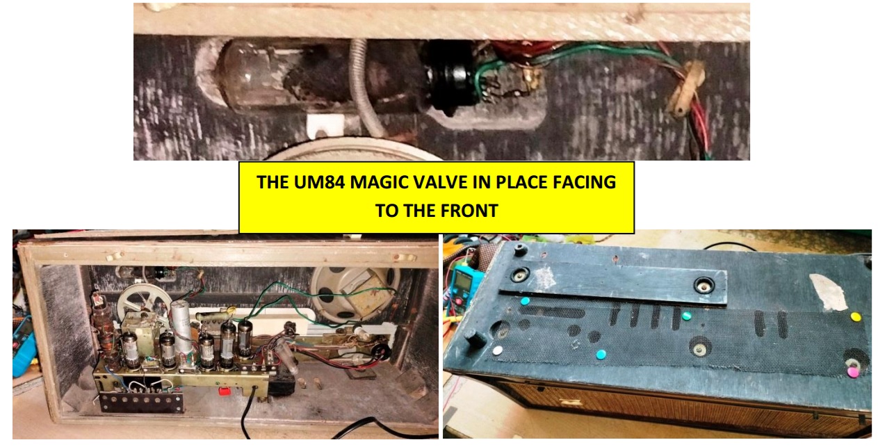
Allowed the radio to work for hours before fixing the back cover. (You won’t find the extended antenna wire in the above picture as it was done later, before fixing the back cover)
Restoration mission accomplished with vigor and enthusiasm and got qualified for prestigious collection. Are you all not happy to see the nostalgic Radio shining like new and to know that it was back to perfect working condition?
P.S. Since reversal of the two pin plug might bring line to the chassis and the antenna wire, I gave adequate caution to the user and also provided a line tester which makes beep sound and flashes on detection of AC. Then inserted the two pin to a 3 pin adaptor and told him to ensure that the line is always on the right side of the plug, which is the standard.

This article was prepared for you by Parasuraman Subramanian from India. He is 74 years old and has more than 30 years’ experience in handling antique equipment like Valve Radio, Amps, Reel Tape Recorders and currently studying latest tech-classes conducted by Kerala State Electronics Technicians’ Association. He has done graduation in BBA degree, private diploma in Radio Engineering and retired as MD of a USA company. Presently working as Consultant to Hospital and other institutions.
Please give a support by clicking on the social buttons below. Your feedback on the post is welcome. Please leave it in the comments.
P.S-If you enjoyed reading this, click here to subscribe to my blog (free subscription). That way, you’ll never miss a post. You can also forward this website link to your friends and colleagues-thanks!
You may check on his previous article on Restored A Tampered CD Player MICROMEGA CD-10 Silver
 (38)Dislikes
 (0)
(0)
10 Comments
Leave a Reply


albert van bemmelen
October 25, 2025 at 6:31 pm
You Parasuraman, and the interested buyer took a very long risk for waiting so many years before the Murphy valve radio finally was ready for pickup.
But seeing all the work done I'm sure it was all worth it!
Parasuraman S
October 25, 2025 at 9:15 pm
Yes, the net result brought broad smiles on both of us. Many thanks for your comments, dear Albert!
DAVID PENTIN
October 25, 2025 at 7:36 pm
Hello , I loved your article on the restoration of the valve radio! I love working on and building valve projects there is much enjoyment on working on equipment that has components which are large enough to see them without straining my eyes and valve radios have a feeling of being alive as they light up and give that dusty resin smell from the wooden cabinets!
Thank you ,
David Pentin
Parasuraman S
October 25, 2025 at 9:18 pm
Yes, working on a Valve Radio is always a thrill. I adore its look and feel apart from the smell that you mentioned! It provides nostalgic feelings too! Large components are very easy to see and replace, rather than the eye straining tiny SMDs that require special microscope to see and other special tools to handle. Many thanks for your comments!
Andy Shiekh
October 26, 2025 at 12:34 am
Wild that the chassis can be live.
Parasuraman S
October 26, 2025 at 3:19 pm
Yes, it was a risk associated with such radios designed in the early stages. We too had one philips valve radio in the home when I was in the school. There was a line tester kept near it and we were supposed to touch the radio only after ensuring that the knobs are not giving a shock! Though there was a written warning behind the back cover, many people had got shocks from such radios, but not heard of any death or bad injuries.
Mark J
October 26, 2025 at 3:05 am
Parasuraman another great restoration article. I have never worked on or repaired valve radios. Thank you for sharing.
Parasuraman S
October 26, 2025 at 3:20 pm
I wish you will get a chance soon! Many thanks for your loving comments, dear Mark!
Yogesh Panchal
October 27, 2025 at 12:00 am
Good Job! Sir,
Thank you! for providing antique experience.
Parasuraman Subramanian
October 27, 2025 at 1:52 pm
It is my pleasure, dear Yogesh Bai! Thanks!