
Tuning Diode (VARACTOR DIODE) Found Short In PANASONIC RQ543ADS TWO-IN-ONE

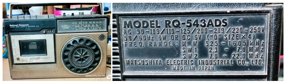
This antique two-in-one made by National Panasonic, which was a hot sale during the yesteryears was brought by a regular customer with a request to see whether the set can be brought back to good working condition. The complaint was that the sound output was very low, even which deteriorated after a few minutes play. When I checked, the sound output indeed was too low.
Anyhow, I opened the four screws on all the four sides of the front cover, for which we need to eject the door, remove the tuning knob from the side and locate the flat head small screws. There was no long screw from the behind to the front cover. Let us have a look at the dismantled set of this lovely antique set.
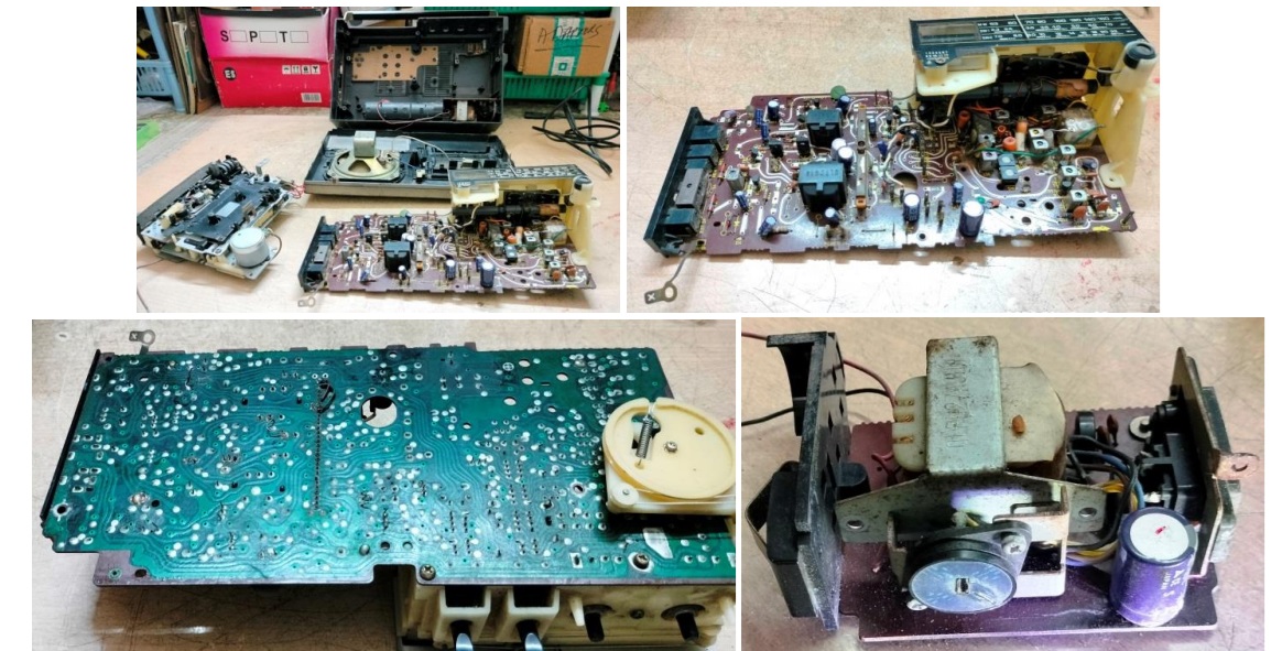
I began my work from the power supply section. Look at the condition of the capacitor which I could see only after removing it:
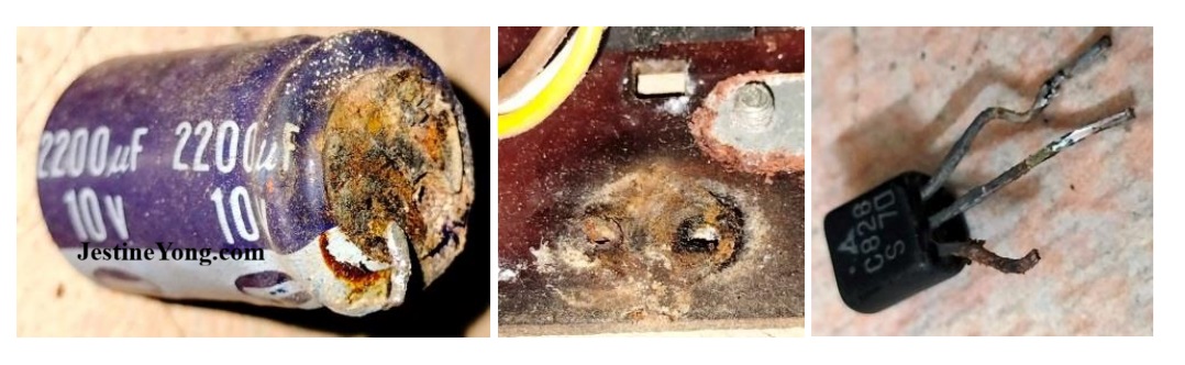
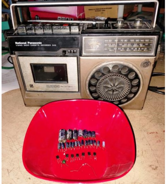
So, I replaced all the electrolytic capacitors on the board, wondering how the set was found working, even when the condition of the filter capacitor was like this! After finishing that, I retouched the entire board thoroughly.
Happened to see a rusted transistor too, picture of which I have given above. After all these exercises, I applied power and checked what was the condition of the set in Radio mode. The sound output was still very low. I fed signal to the amplifier section and checked and found it to be weak. I removed the same type of transistors and replaced it with C945 as exact replacement was not available. After all the four transistors were replaced, one of which was getting hot too, the sound output in the amplifier section was good enough. But the Radio section did not work very well in all the three bands. So, I retuned the IFT and checked. But still then there was no improvement. I used my oscilloscope and checked the signal output at the OA79 (detector stage) and found that the signal was very good at the IFT output, but was dropping immediately after the detector diode. I suspected the diode and replaced it. There was no improvement.
Tracked and found that one of the printed resistors on this double-sided board had lost contact. Boards with printed resistors were very popular those days. Here you can have a closer look!
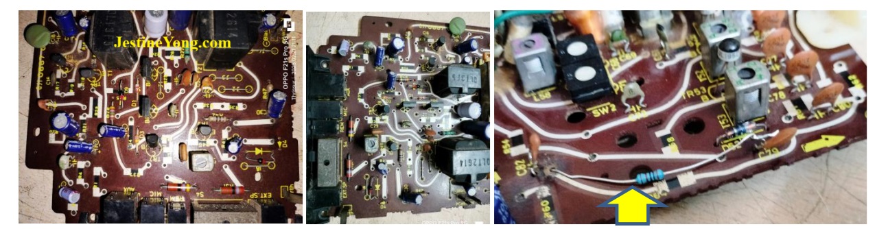
The white line what you see on the board is a protective paint applied on carbon tracks which are inter connected to the other side copper tracks that hold the soldered leads of through hole components. Only resistors were carbon printed on the top side. Some of you might get amused to see these, am I right? The 1K resistor that you see on the third picture is the replacement done by me to restore the contact. Though there was improvement, the output from Radio was not good enough. I checked the amp again and found it to be sound enough! Then my attention was drawn by a varactor diode I found in the AFC circuit. Let us have a look at it:
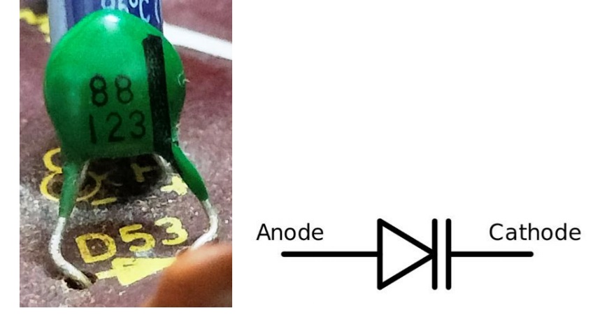
Any of you have seen this type of component before? This type of diode-capacitance fusion was used for AFC and tuning also. SMD versions of this are used now-a-days in digital tuning circuits. In fact, I was surprised to see this type of a component in an antique radio. I removed it and checked and found it was showing reading like a diode. Looking through the various datasheets of varactor diodes available in the web and also looking at its symbol given above, it should not show any continuity, as a capacitor should block it. So, I tried to get a replacement in vain. None even knew the existence of such a component! Anyhow, the radio worked perfectly well when I removed this component and I retuned the set very well. What a strange result!!!!! There was no overloading or jarring even at full volume! How do you like that? Here is the work of IF and RF tuning done:
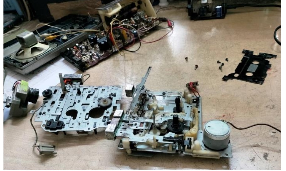
Anyhow, having made the radio side working very well, I focused my attention to the tape mechanism. It was stuck and I had no other go except to dismantle the whole thing:
Cleaned and lubricated the parts, used IPA to clean the belts and rubber rings and pinch roller. Re-assembled the mechanism after a few attempts, as the levers might have to seat properly in the slots for proper function of the press to engage switches. Played a cassette and found that also working really very well! I adjusted the azimuth of the head to get distortion free peak sound output. Fixed the board and mechanism back as how it was.
Closed the set fixing the four screws and played it again for sufficient time in Radio and Tape Recorder mode and found it to be working excellently, qualifying utmost satisfaction to get entry into the prestigious, now world renowned collection bag! (LOL)

This article was prepared for you by Parasuraman Subramanian from India. He is 74 years old and has more than 30 years’ experience in handling antique equipment like Valve Radio, Amps, Reel Tape Recorders and currently studying latest tech-classes conducted by Kerala State Electronics Technicians’ Association. He has done graduation in BBA degree, private diploma in Radio Engineering and retired as MD of a USA company. Presently working as Consultant to Hospital and other institutions.
Please give a support by clicking on the social buttons below. Your feedback on the post is welcome. Please leave it in the comments.
P.S-If you enjoyed reading this, click here to subscribe to my blog (free subscription). That way, you’ll never miss a post. You can also forward this website link to your friends and colleagues-thanks!
You may check on his previous article on No Power In Car Radio AMP SAMCON CDSN555 Solved
 (26)Dislikes
 (0)
(0)
12 Comments
Leave a Reply


Arunkant L Pandit
November 29, 2025 at 3:37 pm
I am having this model in working condition, but sound output is low. This article is useful to trouble shoot the unit.
Thank you very much for sharing Sir.
Parasuraman S
November 30, 2025 at 12:31 am
Glad to know it was useful! Many thanks for sharing your comments!
Yogesh Panchal
November 29, 2025 at 4:42 pm
Good Job! Sir,
You refreshed our old memories.I had this national tap recorder model 543 it was scraped by me in i think 1993 i don't remember exact reason.Varector Diodes are used for compact, reliable,and noise-free tuning in radios & rarely it damage.
Parasuraman S
November 30, 2025 at 12:32 am
Yes, very nostalgic! Many thanks for your comments, dear Yogesh Bai!
Albert van Bemmelen
November 29, 2025 at 7:02 pm
It would be a strange mystery if this radio cassette recorder still wouldn't play after you replaced all those parts and your as always excellent skilled engineering restoration work! I only wonder why you thought that the odd looking part was a varicap or varactor diode because it as you already noticed certainly didn't look like one?
I guess that those bad functioning carbon components are often still found on layers in the cheaper made IR TV remotes.
Parasuraman S
November 30, 2025 at 12:35 am
Many thanks for your expert comments, dear Albert!
Mark J
November 30, 2025 at 5:15 am
Parasuraman great repair and restoration. These type of articles are very helpful.
Parasuraman S
November 30, 2025 at 9:49 am
Many thanks, dear Mark!
Lawrence Mc Coig
December 1, 2025 at 11:28 pm
Doing good work with your hands is a large reward. Many young ones never know this satisfaction.
Parasuraman S
December 2, 2025 at 4:34 pm
Exactly! That is the fuel to keep our engine chugging on in all cylinders! Many thanks for your comments!
Muykit
December 3, 2025 at 12:59 pm
Indeed some little known components may be found in electronic circuits, squeezed among other components, hence turning troubleshooting into a nightmare. A technician may lack the know-how of determinig the integrity of say a diode varactor. Worse still there may be no symbol marking for the component, or even, a misleading indicating mark. Now you are left staring at an impending crisis. The radio you fixed bears a close resemblance with a certain JVC radio my father had in 1986, what a mesmerizing bass sound it had !
Parasuraman S
December 4, 2025 at 10:53 am
Many thanks for your comments enriched with nostalgic recollections and facts of experiences!