
1.8V Voltage Regulator IC Problem In LED Monitor

The complaint was no power. This LED Monitor uses an external power adapter and the output voltage was tested good (19 volt DC).
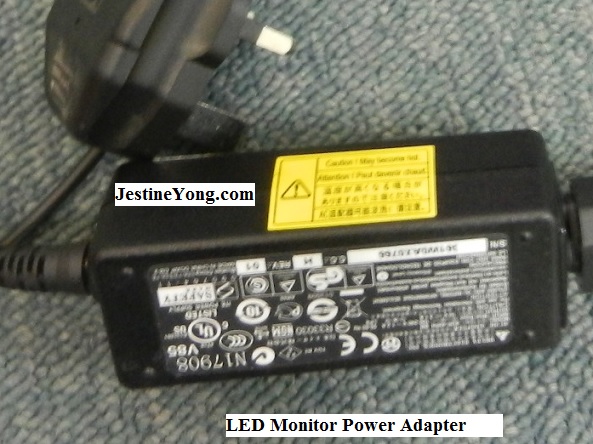
Since the power adapter was tested good, I had to open it up and check on the mainboard.
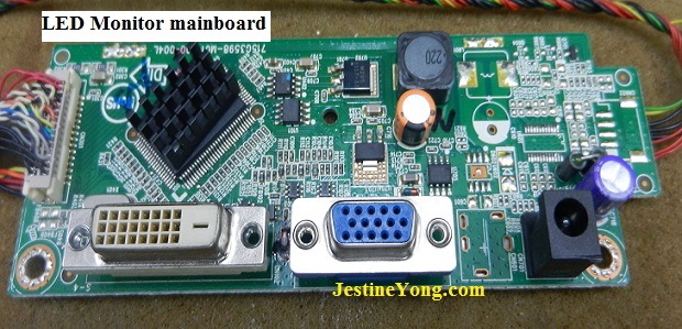
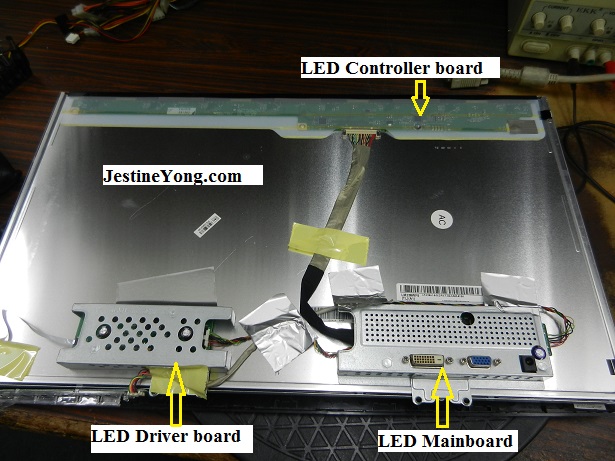
If you take a look at the photos below, this Monitor consisted only three circuit boards- the mainboard, LED backlight driver board and LED controller board.
Since this is a LED Monitor so you would not find an inverter board. Inverter board is for LCD Monitor.
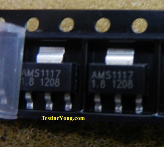
Once the metal cover of the mainboard was removed the first thing I do was to check for the SMD voltage regulator ICs. I saw two ICs ie; 1117-3.3 (output 3.3 volt) and 1117-1.8 (output 1.8 volt).
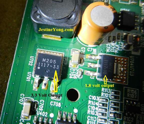
I began to test on these two ICs and found the 1117-3.3 was good but 1117-1.8 IC does not produce any output voltage. It has 3 volt input but no output. Both ICs datasheet you can find it from the internet. This was a good sign because if there was no output from this IC means the MCU IC would not work. If the MCU IC doesn’t work means it will not generate any signal to the power LED light.
Before I replace the faulty 1117-1.8 IC I measured between the ground and the IC output (pin 2) with an Analogue meter set to x 1 Ohm. It gave a high and a low reading which was good. If I get two similar low Ohms reading this means there could be something shorted that had caused the 1117-1.8 IC to stop producing output voltage.
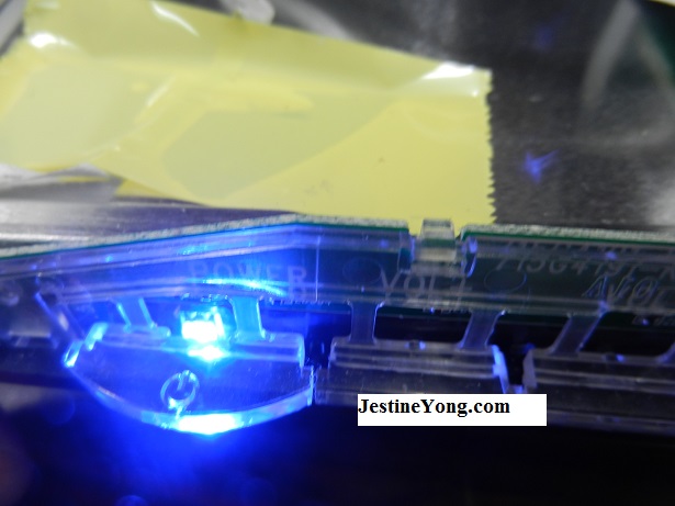
It was easy to replace this small SMD IC and after replacement was done and powered On, I could see the blue power LED light.
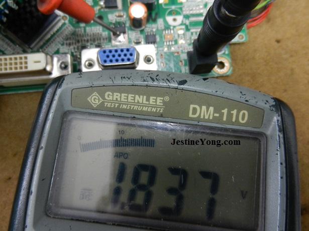
When I measured the voltage it showed 1.837.
If you want to become an expert in LCD/LED Monitor repair you can check out my ebooks below:
http://www.LCD-Monitor-Repair.com
and
http://www.LCDMonitorCaseHistories.com
Jestine Yong

Please give a support by clicking on the social buttons below. Your feedback on the post is welcome. Please leave it in the comments.
P.S- If you enjoyed reading this, click here to subscribe to my blog (free subscription). That way, you’ll never miss a post. You can also forward this website link to your friends and colleagues-thanks!
 (213)Dislikes
 (0)
(0)
42 Comments
Leave a Reply


Robert Calk
April 24, 2015 at 4:36 pm
Good job Mr. Yong.
Jestine Yong
April 24, 2015 at 4:42 pm
Hi Robert,
You are welcome.
Jestine
Edward
April 24, 2015 at 9:35 pm
Hi ther mr Yong I have this samsung 943NXPlus lcd monitor which only shows a flickering power light and the screen does not light up when I open it I replaced 2 bulged caps but before I removed the caps I heard a huzzing or sizzing sound that's cuming frm the transformer or the inverter transformer and can you tell me if I can replace a resistor fuse wif a normal resisitor please help
Jestine Yong
April 24, 2015 at 10:20 pm
HI Edward,
Resistor fuse is flameproof type and not recommend to use normal resistor which can easily burn.
Jestine
DIPTEEKANTA MAHAPATRA
May 21, 2015 at 8:18 am
dear Jestine yong
in my CRT monitor screen.a vertical line is showing.and no picture will be shown.what's the matter.can you help me to solve this problem.
Jestine Yong
May 22, 2015 at 7:41 am
HI Depteekanta,
Vertical line is the problem of horizontal section. Try check the horizontal yoke coil area for dry joints and make sure the horizontal yoke coil is not open circuit.
Jestine
Albert Hoekman
April 24, 2015 at 5:05 pm
Nice explanation, first time I read about this fault. Mostly the problem is with the external power supply.
Jestine Yong
April 24, 2015 at 5:48 pm
HI Albert,
Yes the no power symptom also can be caused by bad mainboard.
Jestine
Yogesh Panchal
April 24, 2015 at 5:28 pm
Sir thanks your tips.
Jestine Yong
April 24, 2015 at 5:48 pm
Hi Yogesh,
You are welcome.
Jestine
Anthony
April 24, 2015 at 5:29 pm
Hi Jestine, precision diagnosis and repair...nice work !
Jestine Yong
April 24, 2015 at 5:49 pm
HI Anthony,
Thanks.
Jestine
Waleed Rishmawi
April 24, 2015 at 5:51 pm
Thanks for the nice article and for the nice photos. congrats on your success. God bless.
Jestine Yong
April 24, 2015 at 8:48 pm
Hi Waleed,
You are welcome.
Jestine
yaghob
April 24, 2015 at 6:09 pm
hi
really nice article
very thanks
i hope see LCD Monitor Case Histories ver 4! as soon as possible
Jestine Yong
April 24, 2015 at 9:24 pm
HI Yaghob,
You are welcome.
Jestine
Phumlani
April 24, 2015 at 6:18 pm
Nice Work Sir
Jestine Yong
April 24, 2015 at 9:24 pm
Hi Phumlani,
Thanks.
Jestine
moshe
April 24, 2015 at 9:07 pm
Hi Jestine
Nicely put!
thanks for sharing
Jestine Yong
April 24, 2015 at 9:31 pm
HI Moshe,
You are welcome.
Jestine
Humberto
April 24, 2015 at 10:06 pm
Hi Mr. Jestine Yong, good repair, you anlaized deeply the Mainboard to find the culprit and finally the LED Monitor was saved from the dump. Congratulations.
Jestine Yong
April 24, 2015 at 10:17 pm
HI Humberto,
Thanks.
Jestine
jose antonio
April 25, 2015 at 2:55 am
Mr. Jestine great job, thanks for sharing
Jestine Yong
April 25, 2015 at 8:50 pm
HI Jose,
You are welcome.
Jestine
Paris Azis
April 25, 2015 at 4:57 am
Hi Jestine,
"Logical thinking = effective troubleshooting"...(Once again confirmed)!
Good job!
Best Regards
Jestine Yong
April 25, 2015 at 8:48 pm
HI Paris,
Thanks.
Jestine
Ernst
April 25, 2015 at 6:37 am
Hi Jestine,
Thanks for sharing this with us. This way i keep on learning all the time
Jestine Yong
April 25, 2015 at 8:48 pm
HI Ernst,
You are welcome.
Jestine
Arshath
April 25, 2015 at 1:24 pm
Hi jestine sir.....u are dng ll sir.....i gathered too many information's from u....nice work....thank u sir....
Jestine Yong
April 25, 2015 at 8:48 pm
HI Arshath,
You are welcome.
Jestine
Rajesh
April 25, 2015 at 3:14 pm
Thanks a lot dear
Jestine Yong
April 25, 2015 at 8:49 pm
HI Rajesh,
You are welcome.
Jestine
Veyron
April 25, 2015 at 7:16 pm
That was an awesome solution from you again.
I learnt a lot from your post. But this time I could not understand one part and that's :
"Before I replace the faulty 1117-1.8 IC I measured between the ground and the IC output (pin 2) with an Analogue meter set to x 1 Ohm. It gave a high and a low reading which was good. If I get two similar low Ohms reading this means there could be something shorted that had caused the 1117-1.8 IC to stop producing output voltage"
What it mean by "it gave a high and low reading".I mean does the meter shows a high when we first connect to the pin 2 and later drops to a low value or is it like we take two separate readings and first we get a high value and the second time a low value. Please explain me this, its the first time ever I read anything like this.
If possible can you upload a video or photos explaining hows this done.
Jestine Yong
April 27, 2015 at 7:19 am
H Veyron,
It means that if the dc output line is shorted there will be two similar readings. If it is normal it will usually have a higher ohm and lower ohm value when you reverse your probe and test. I suggest that you visit this link for more information https://www.jestineyong.com/audio-interface-repaired/
Jestine
Aziz
April 26, 2015 at 6:13 pm
Hello dear Mr.Yong , thanks for sharing different types of electronic device repairing.God bless
Jestine Yong
April 27, 2015 at 7:14 am
HI Aziz,
You are welcome.
Jestine
Abdul Kader
November 17, 2015 at 6:41 pm
Thank u boss
Feroz tejani
September 7, 2017 at 2:04 am
Sir can you please explain the different voltages of an lcd/led tv motherbord like 3.3v ,1.8v etc and to which sections these voltages are used for
diwa
September 18, 2017 at 10:05 pm
sir,
my acer ph660 monitor voltage is unstable even in direct line without vga attached the screen shakes and rolls, could you suggest me is it the capacitor problem? i m in trance.
Jestine Yong
September 21, 2017 at 11:09 am
HI Diwa,
Without hands on assessment I would be really guessing on what might be wrong. Unstable voltage problem can be caused by many factors. I suggest that you check the output filter capacitors with esr meter.
Jestine
Fed
February 22, 2023 at 9:43 am
Hello,
This was a great lesson, and quite rare too. Nobody on the internet, has ever explained how to test an SMD voltage regulator IN-CIRCUIT - so, thank you very much!
But I have two questions:
1- When you say: “I measure between THE GROUND and the IC output (pin2)…” Do you mean, the ground pin of the 1117 1.8 OR do you mean, a ground spot/point somewhere on the circuit board?
2- And what do you mean, when you say: “It gave a high and a low reading which was good…” HOW are you getting two readings, what did you do exactly? - please clarify the procedure, in detail.
Thank you kindly
Jestine Yong
March 6, 2023 at 4:54 pm
Hi Fed,
1- When you say: “I measure between THE GROUND and the IC output (pin2)…” Do you mean, the ground pin of the 1117 1.8 OR do you mean, a ground spot/point somewhere on the circuit board?
Both are the same coz both grounds are cold grounds (metal casing).
2- And what do you mean, when you say: “It gave a high and a low reading which was good…” HOW are you getting two readings, what did you do exactly? - please clarify the procedure, in detail.
When the VCC line is shorted to ground you will get two similar low ohms readings (either way) using Analogue meter set to x1 Ohm. If the VCC line is not shorted you will get a higher and a lower Ohms reading when you reverse the probes.
Jestine