
Repair and Working Principle of IC LM 324-Based on Sensors IR & LDR Automatic Lighting Controller
This machine is designed to detect motion with in a rang about 6 meters and convert any movement in to electrical signal.
With help of IC LM324 an operational amplifier and a relay, the circuit switches lights ON or OFF for a specified time. It uses both an LDR (light Dependent Resistor) and an infra-red IR sensor to detect changes in light and human presence, making it ideal for parking zones, stairways and other building automatic applications.
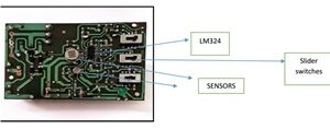
LM 324
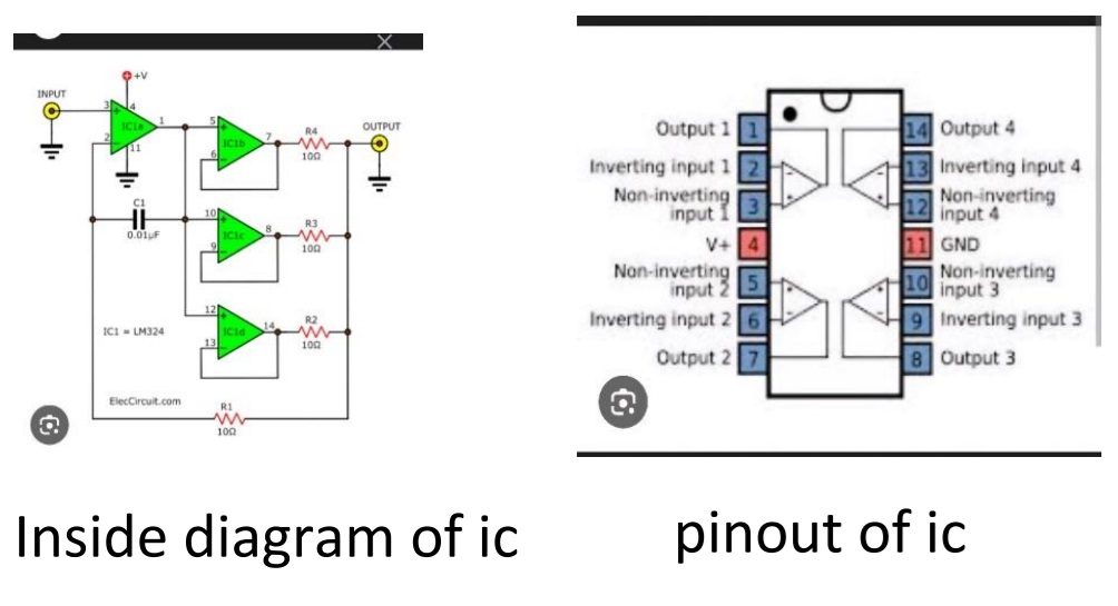
The LM 324 contain four independent operational amplifiers in single 14-pin package. It compares voltages and make switching decision. In this machine, it processes the signals from both the IR sensor and LDR to decide whether to trigger the relay or not.
Part list of machine
1 MKT cap .47 microfarad 250 volt
Ceramic cap code. 102 250 volt
Plastic cap code 33 Nano 400 volt
Resistor 120 ohm 2 watt
Resistor 120 ohm 1 watt
Electrolyte cap 220microfard 35 volts
Electrolyte cap 1000 micro farad 16 volts
Zener diode 25 volts
Zener diode 7 volt
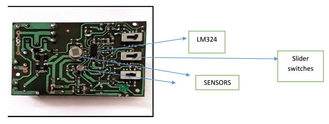
SENSORS
PIR IR D 204 B
LDR
IC LM324
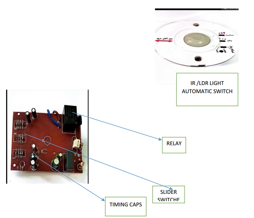
Relay code no F3FA 25 VOLT 10A
Green power LED
Three slider switch for user to get best result
Working principal of machine
The IR sensor detects infrared radiations emitted by persons, while the LDR senses changes in light intensity due to motion these signals are convert into voltages and fed the LM324 ic op-amp. Which compare them with preset threshold voltages and determined whether to active the relay.
How 25 volts of psu reach to relay and live line and connects to the lights:
IR sensor by detecting the IR rays that emitting from the persons and motions that detect by LDR these changes produce millivolts in both two sensors and these signals reach to pin 12, 13 IC LM 324. IC by comparing these voltages by threshold voltages and if these are exceeds the threshold voltages order to pin 14 to release the 7 volt of power supply to the circuit ,7 volts reach to base of smd transistor CR and turn it on transistor act as a switch and let 25 volts from PSU go through and reach to the coil of relay ,relay act as switch the result is live line connection with 0ut going line to the lights REPAIR
The machine was initially non- functional
Both zener diode 25 and 7 were good that means psu is intact. I also touch all the joints by hot soldering iron and even with solder again this machine. warranty was expired on 2023. The Green led that shows the power now is on here.
But No sign of detection from machine Comparing the results of voltages reading on pins of ic before and after replacement the ic is as follow:
pinno1 6.37 this is out put
pin2 -2.34 up to 2.76 this is input pin unstable voltages
pin 3 – 3.38 input pin
pin4 – 6.77 this is Vcc pin
pin 5 -2.76 input
pin 6-2.76 input
pin7 -1.84 up to 3.75 unstable output voltages
pin8- 0.5 up to 0.58 unstable output pin
pin9 -0.58 input pin
pin10- 0.58 input pin
pin11-GND
pin12 -6.23 input pin
pin 13-6.61 input pin
pin14- 00 output pin
Since ic showed unstable voltages on it was replaced with a new one after installation of new ic I got following voltages:
pin1- 6.41
pin2-2.66 and stable
pin3-3.36
pin4- 6.77 Vcc
pin 5- 2.77
pin6-2.78
pin7-2.67 and stable
pin8-0.54 and stable
pin9-0.57
pin10 -0.58
pin11- GND
pin12-6.23
pin 13 -6.74
pin14-00
after replacing the ic I received improvement on pins2 ,7,8 but still pin 14 showed no out put by testing 2 sensors i found out that LDR sensor is good but IR sensor despite of receiving the supply voltages does not have any output I replaced the IR SENSOR and after that machine start to work again slider switches also replaced with good ones.
3 SLIDER SWITCHS
In this machine for user also installed three slider switch to reach the best performance and also each switch has three modes switch no 1 time control
FIRST MODE
Determine how long the lights remain on after activation.
Switch with 3 mode
The RC resistor –capasitor circuit determine the ON duration using formula t=RXC

As long the cap is charging the pin no 14 maintain 7 volts then the relay is on the lights are on when the cap fully charged the voltages and inputs to ic changed and the ic go to Cutoff the 7 volts from pin 14 and lights will turn off.
Switch no 2 is Sensitivity control
Allow the user to set detection sensitivity at good better best level
The out put from pin 8 of ic directly is going the slider switch
Different resistor divider circuit s adjusts the voltage going to each sensors
Lower voltages —-> lower sensitivity
Higher voltages —>higher sensitivity
Switch no 3 operating mode
The switch selects between three lighting mode all the day mode
When user need all around the day and night all the lights on by putting slider switch to this mode switch simply select a circuit and bypass the ic and directly connect to psu to relay and live line to the lights.
1. Second mode morning mode
2. Activate lights only when morning light intensity changes
3. Use an RC circuit and threshold adjustment for gradual response
Third mode or night mode:
Operate when ambient light falls below threshold. The LDR works with the LM 324 to trigger lighting during low light level.

This article was prepared for you by Mr Beh from Iran
P.S- Do you know of any your friends who would benefit from this content that you are reading now? If so, forward this website to your friends or you can invite your friends to subscribe to my newsletter for free in this Link.
Note: You can check his previous article on How I Repaired SONY TV Power Supply Model: T370XW02 Made In Taiwan
 (32)Dislikes
 (0)
(0)
6 Comments
Leave a Reply


Albert van Bemmelen
October 18, 2025 at 6:23 pm
Glad to hear from you again after a long time by presenting this quite detailed automatic lighting controller repair Mr.Beh!
I suppose you afterwards also easily were able to check the now replaced LM324 in your opamp tester to confirm it was defect?
Replacing the defect PIR sensor was to be expected since on average those well-made PIR sensors can only last between 5 to 10 years anyhow.
Parasuraman S
October 18, 2025 at 6:40 pm
Very useful and educative article! Many, many thanks for writing such a detailed informative article with relevant guidelines.
Abdul
October 18, 2025 at 7:45 pm
Impressive, good Job
Best regards
Yogesh Panchal
October 18, 2025 at 10:05 pm
Good Job!Beh
Mark J
October 19, 2025 at 3:40 am
Mr Beh good informative article. Thank you for sharing.
Behzad
October 20, 2025 at 10:23 am
Hi All
Thank you so much of your supporting comments
Rgrds
Beh