
Complex SMPS Of HP Latex Printer – DELTA ELECTRONICS C1106-60002
This was brought by a new customer as per recommendation of another regular customer of mine. The complaint reported was that the standby green LED was lit but no commands from the front display panel of the printer was responded. Usually, the standby led would light up, when switch on the display panel is pressed and the amber led will light up and the next blue led would flash once. Afterwards, when print command is executed, the blue led would get lit and printing process would start. The company sent him a standby mother board, printer board and display board as these were suspected. He replaced the boards one by one but nothing worked. The company service team mentioned that the power supply unit had to be replaced for which they would send a refurbished one. No board level service was undertaken on the SMPS. He got the power supply and the old boards which were there in the printer worked on that, confirming that the PS was the culprit. That’s how it landed on my table as the customer did not give the old one back on exchange and intended to keep it as a standby. He paid the difference also to the supplier.
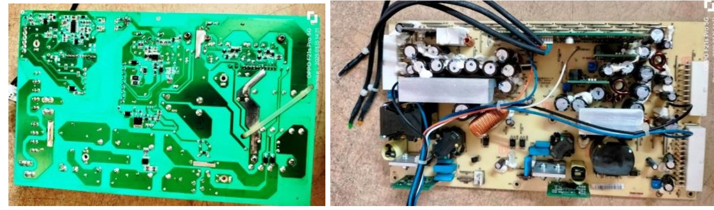
Well, let me be frank, I have never seen any SMPS so complex in my lifetime. There were two boards inside. One was taking care of the primary power supply as well as partial processing of the primary functions of yet another section on the other board. I saw a few vertically fit boards, several SMD ICs and components on various sections. As usual, no schematic or service manual was available in the web and I could not get one also through my techie friends. I dismantled the boards.
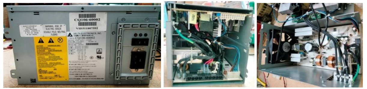
Let us have a look at the inside before continuing:
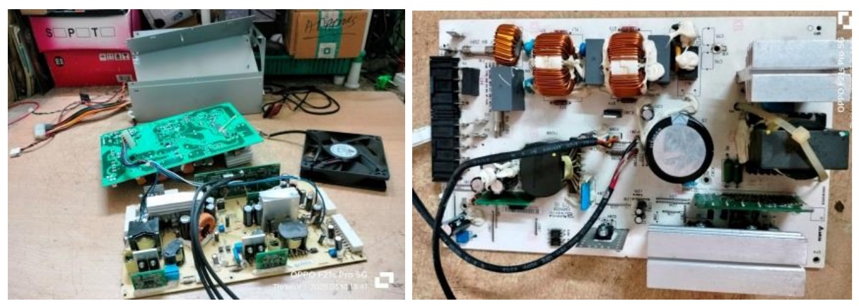
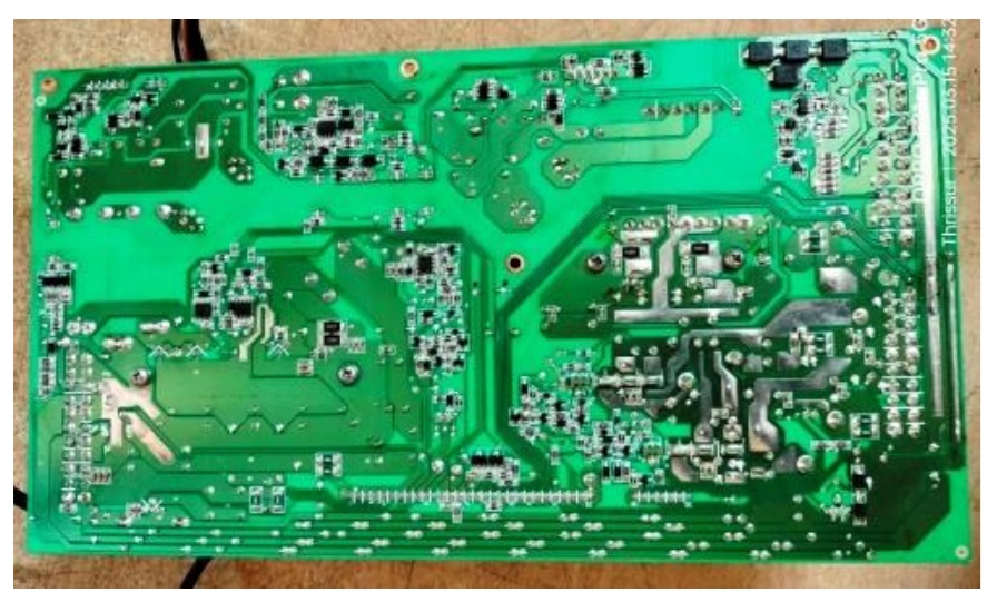
Tried to study how the inter connections are made and what are the functions handled on the second board, which seemed to be handling the PFC and other supplies required. The outputs that I could see on the boards were 3.3V, 5V, 12V and 48V.
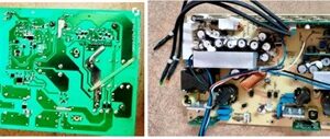
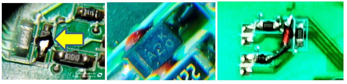
48V could be for the printer section. I could see buck boards for 3.3V and 5V fit vertically. There was a large board fit vertically with several SMD ICs, transistors and other components, which could be processing the commands. On careful scrutiny of the boards with a lens, I could find a diode burst near the optocoupler on the AC power in board (first picture below). Only a portion showing KO was there and on checking other sections, I could see many other diodes with KO markings, which had A2 as the number (Giving one such in the second picture below). On verification in the web, I learnt that it could be a Zener diode of 5V or signal diode like IN4148. Since the other side of the diode was not earthed, it could only be an IN4148. So, I soldered one there as replacement
The customer brought the display board, mother board and the printer board for me to study further. The mother board looked like a computer mother board, with the same ATX PS connections, but a few wires were of different colours and placement was also different. Let us have a look at the comparison:
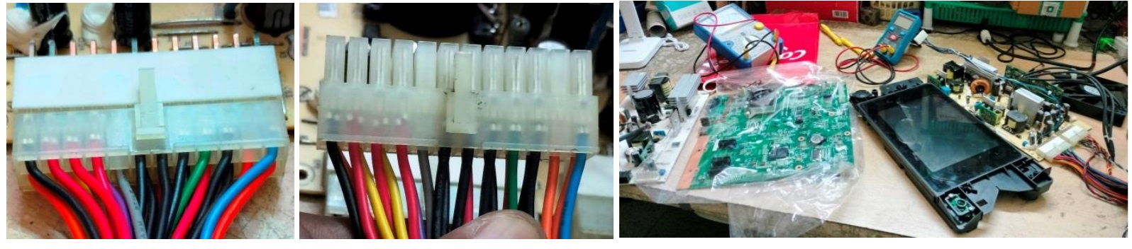
The first picture is that of the 24 pin connector of the HP printer and the next one is that of an ATX PS lying in my stock. But the green wire and black wires were in the same place. I inter connected the boards brought by the customer and applied power and pressed the on/off switch on the display panel. Nothing happened. Checked whether the on/off switch was functioning and found it to be perfect. So, something was wrong. The customer took back the other boards for returning it to the company. Anyhow, I confirmed that the green wire and black wire in the middle had to be shorted for the power on like any other ATX PS and that’s all what I wanted to know for further checkup.
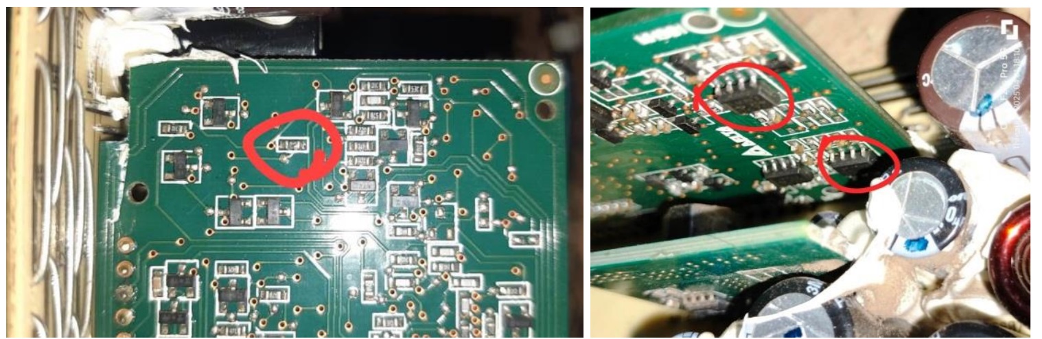
I spent several hours in checking almost all components and removed a couple of vertical boards and could not find any defects. I did not remove the large vertical board at that time. The normal function could be that on release of the PS from the standby, the PFC voltage should get built up and the amber light would get lit. Though I knew that the problem could only be in the control board, I did not remove it and check it as I had a number of other works like TVs to attend to and my mind shut down on this due to other priorities. Afterwards, when I became free, I decided to take it to my techie friend staying around 60Kms away from my home, for which I sought his appointment as he was an extremely busy person doing work on several company boards. We spent time together on the boards once again studying the functions. He removed the control board and subjected it to checking under a powerful lens and found that a 10K resistor was burst. He traced that it went to two LM393 SMD ICs on the other side, which definitely needed replacement:
He did not have stock of these and he even went to one of his friend’s house nearby in search of it. Getting spares meant that he had to go a long distance, which he preferred always to pool in the requirements and get it together to make it economically viable and of-course, to save valuable time. So, I returned and arranged to fetch the replacements, which came to my hands after a couple of days.
Then I sent the ICs to him through speedpost. He later confirmed that after changing the ICs, the PS started working fine, which was a good news. He sent the boards to me by courier, which I got after a couple of days due to intermediate holidays here. I checked the board by shorting the power-on pins and found it to be working fine. Reassembled the boards back in its case, closed it and applied power shorting the power pins:
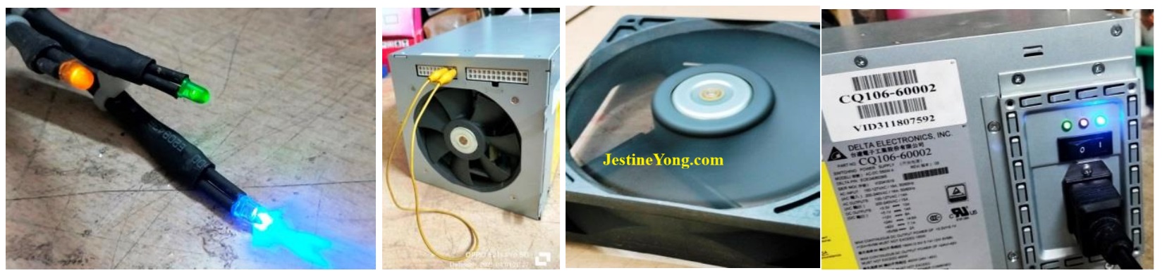
Mission accomplished and satisfaction had every reason to gain entry into the collection bag!

This article was prepared for you by Parasuraman Subramanian from India. He is 74 years old and has more than 30 years’ experience in handling antique equipment like Valve Radio, Amps, Reel Tape Recorders and currently studying latest tech-classes conducted by Kerala State Electronics Technicians’ Association. He has done graduation in BBA degree, private diploma in Radio Engineering and retired as MD of a USA company. Presently working as Consultant to Hospital and other institutions.
Please give a support by clicking on the social buttons below. Your feedback on the post is welcome. Please leave it in the comments.
P.S-If you enjoyed reading this, click here to subscribe to my blog (free subscription). That way, you’ll never miss a post. You can also forward this website link to your friends and colleagues-thanks!
You may check on his previous article on Attempts To Save Two Computer Monitors Failed – LG 16M35A-B & ACER P166HQL
 (41)Dislikes
 (0)
(0)
5 Comments
Leave a Reply


Albert van Bemmelen
November 22, 2025 at 4:25 pm
After reading about checking all these complicated original HP power boards I'm glad that the extra miles you had to go in the end paid off.
It is a shame that HP doesn't share any service manuals. Especially since disassembling office desktop printers already is complicated and timeconsuming enough, and for me reason to no longer buy this brand. After my first inkjet Epson Stylus 600C that stopped working after only 13 months (without any service or warranty afterwards from Epson at all!), followed by problematic HP720C and HP840C printers that refused to work on many brandnew bought ink cartridges, I now use a much better Brother DCP-385C inkjet printer.
Parasuraman S
November 22, 2025 at 7:30 pm
High brand products always muzzle their way out like this, and consumers like us get hit! Good decision to buy Brother, though part availability would still be a question. Many thanks for your expert comments, dear Albert!
Yogesh Panchal
November 23, 2025 at 11:42 pm
Sir,
Glad to see a happy ending, though it was a very complicated job, now a days no brand is doing component level repair on customer's end, yes they do it on the product they buy back and use it for another under warranty failure device.
Hope you get a good return for this work.
Parasuraman S
November 24, 2025 at 7:43 pm
Yes. Both of us got well paid by the customer. Many thanks for your involved comments!
Luis
April 30, 2026 at 4:43 am
Which pine trees do you bridge to activate it?