
The Thrilling Experience Of Restoring Antique Valve (TUBE) Radio Murphy Mayfair TAO-684
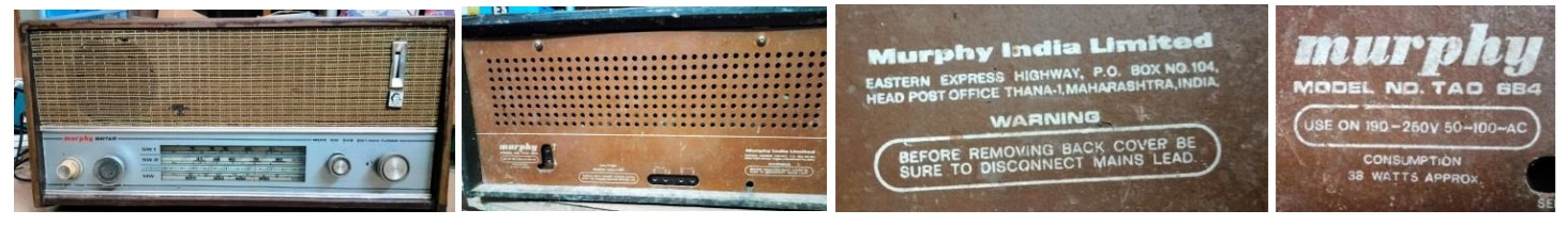
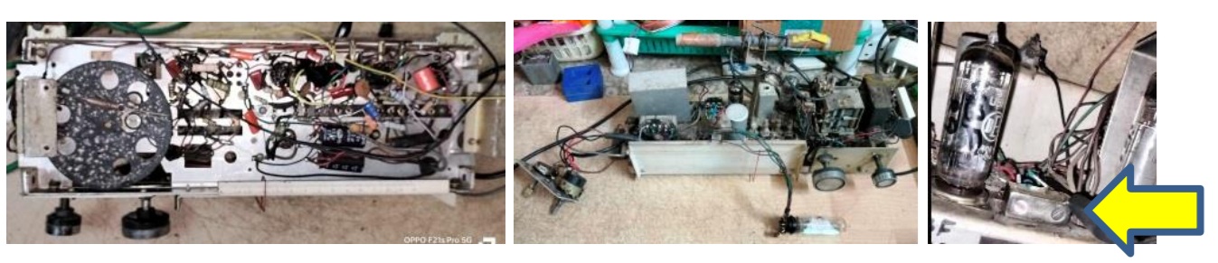
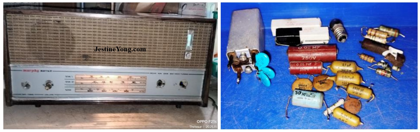
This Radio was picked up by me on my way back from a faraway hospital where I had gone for periodical health checkup of my wife who is recovering from a stroke. The look of the Radio in spite of its age, was very impressive and whoever was the collector must be an antique lover. The customer was an old person involved in collection and re-sale of antique sets and came in to my clientele by a sheer chance. I took it up for repair as soon as I got a gap and did a cleaning of the inside to the extent possible as the wooden cabinet, coils and other intricate connections including the open Metal gang of the Radio are to be handled very, very carefully. Let us have a broad view of the inside:
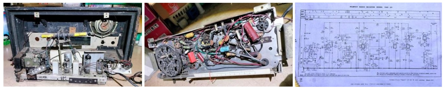
The service manual of the set was available with me in my collections and I am providing an image of the schematic to those who are interested in restoring such sets. The Radio used totally 5 Valves: UY85 as rectifier, UCL82 as preamp & power amp combined, UBF89 as inter IF amp, UCH81 as RF oscillator and Mixer, UM84 as the Magic Valve (Tuning indicator). The filament voltages required for these valves are different fom one another, unlike the E series which have a standard 6.3V.
The advantage is that in U series, the current drawn by the filament is minimal and the AC input is dropped to provide total voltage required for the filaments. For examble let us take this Radio: UY85 = 38V, UM84 =12V, UCL82 = 50V, UBF89 = 19V, UCH81 = 19V. All are rated for 0.1A. The total voltage required for the filaments therefore works out to 138V. So in this Radio an auto transformer is used with one end of it grounded and a tapping is taken at a point where 138V comes out and all filaments are connected in series. A capcitor of 0.047 is connected to the ground as a noise filter. Let us have a look at the extract of filament connection:
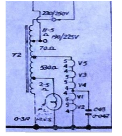
As you can see, a tapping at 2.5 Ohms is taken for the dial bulb and another at 530 Ohms for the 138V. Apart from that a 70 Ohm filter is provided for the main supply to the Radio. The dangerous disadvantage of this type of Radio is that the chassis will get 230V AC directly and might give a lethal shock if the ground becomes the Line in. In those days, a line tester was used by the customers to check whether the chassis was alive and then invert the two pin plug so that the Neutral comes to the ground. Many of you might already know that the Neutral connection is actually an earth connection done at the Power Generating stations. We had a similar Philips Radio in our home during my school days.
My first step was to check whether the AC was coming in and the filaments were lighting up. The Radio had been tampered very badly by some hands before and that made my task more difficult. The on/off switch connection behind the Tone control pot was found bypassed and directly given. The joints had dry solder. Removed, cut and made fresh connection of the wires. All the valves were removed, pins cleaned and sockets sprayed with CRC-20, and valves inserted in & out a few times to enable self cleaning. One of the Two parellelly connected 220 Ohms/10W AC dropping resistors was found broken. It was replaced. There was no sound output when AC was applied ensuring that the Line-in comes to the Auto transformer. Anyhow, I was already using an isolation transformer with an MCB connected to it for my service table and that kept me safe. The next step was to check whether UY85 was producing the required DC voltage. It was very good with a 285V DC and surprisingly the 32+32uF Large Aluminium Cap was also good. But it was found leaking the electrolyte at the bottom when fully charged and it came out with steam like lava, because of which I disconnected that and connected two 33uF/450V under it. The next step was to check the voltages of UCL82. The voltages were abnormal. Found a few resistors open and the 5uF/25V electrolytic capacitor at pin 2 completely dried.
Replaced these, upon which the sound output was ok. Did a general check up of all resistors and found a few more of them open and a couple of them broken. The touch with a screwdriver at pin 2 of UBF89 valve did not bring any result in the speaker. So checked all the coupling capacitors and other fixed capacitors and found these to be either short or completely out of range. Replaced every one of them. The method used was to cut the components as close to it as possible preserving the cut leads in place, then clean the cut leads thoroughly and solder the new componet on these leads. This way, the cumbersome task of pulling of the component leads which are always wound on the joint before soldering and resultant damages could be avoided. After all these works, the touch at the aerial point brought somevery low sound to the speaker, indicating that the connections from that end to the Amp sections was live. The next step was to remove the wax from the IFT alignment screw hole and make the Ferrite core free enough for adjustment.
We have to very carefully insert small pins and remove the wax little by little until it was clean. Otherwise the ferrite core would break! Slowly turned the ferrite cores at both ends of the IFT to bring it a little above the hole. Applied a 452KHz modulated signal to pin 2 through a 0.1uF/400V cap. Then tried adjusting the secondary coil to pass through the signal. But the tuning was not getting done and the sound output remained at same level even though I turned the Ferrite core fully in. The reading of the primary coil was also 17 Ohms instead of 10 Ohms. Disconnected all wires and removed the IFT for further study. Let us have a look at the inside of this IFT along with an extract of the schematic:
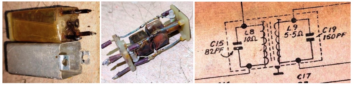
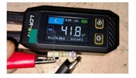
As you can see from the schematic, there is a peaking capacitor of 82pF at primary and 150pF at the secondary. I cut the caps away and checked both of them. The 82pF was perfect. But the 150pF showed short. Let us have a look:
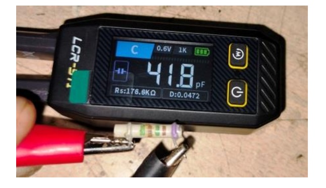
The 150pF was showing 41.8pF! These caps have to put up with high voltages present in the primary, one end of which is connected to the plate of the tube. The high voltage is applied to the coil at the startup point. So, these caps generally fail over a period of time. I was not having an exact replacement. So, took three 101/2KV caps, connected two in series and connected that across the other one. The 101 (100pF) in series will make it 50pF and when this is connected across the 100pF, it will make a total of 150pF. Since these caps were large, I opted to connect it externally.
Then put back the 82pF to where it was. Fixed the IFT back with the peaking cap soldered outside and retried applying the signal. But though the primary tuning was reaching peak, the secondary tuning was not, indicating that the IFT was not good enough and needed replacement. I used an imported universal IFT, modification of which has been explained by me before. https://jestineyong.com/replaced-ift-with-imported-in-philips-valve-tube-radio-model-major/ The tuning was perfectly getting peaked after fixing the new IFT. So, applied the signal at the aerial, keeping the gang fully drawn in and selecting Medium Wave, i.e., to keep the radio tuned at the minimum frequency. I had kept the cores of the input IFT also out and turned them in one by one to get a maximum peaking sound. I did not venture to use my 100Mhz Digital Oscilloscope to test the signals because of the peculiar ground of this Radio. So, relied fully on my hearing. Then tuned the nearest station at that end and adjusted the antenna coil for getting a peak output. The output was superb and I was pleasantly surprised to hear the music in such depth and played the entire program which was songs in different languages including English. I also shared the videos of these songs in my family group and they were all thrilled to see and hear the wonderful sound reproduction. Let us have a look at the bottom of the Radio after finishing the complete work and also the top in which I have highlighted the newly fit IFT:
The gang condenser was shaking and I inserted a temperature withstanding plastic sheet between the gang and transformer and applied Fevibond, a type of rubber glue. Also inserted a few wires to tighten the rubber washer holding mounting screws and applied the same glue so that the Gang was sitting tight enough not to shake while turning the knob at the same time keeping away from its own vibrations due to over tightness that can cause booming effect.
That’s why these are mounted with rubber bushes in the screws. Replaced the burnt out dial lamp with a 6.3V bulb from my stock. Replacement of dial bulb, if necessary should be done at the last stage as frequent on/off would otherwise blow it out. (If the bulb is ok, unthread it to avoid its rear contact and keep it that way until the restoration work is over.) Then mounted the chassis inside the cabinet. Fixed the separate plate that held the Volume & Tone Control pots properly, providing a missing nut. Fixed another missing nut for the speaker and fixed that too on its rubber bushes ensuring proper tightness and that it was shake free. Fixed the bottom cover. Soldered the internal antenna wire to the aerial point, where I had earlier replaced the 471 (470pF) cap. Provided a ground wire for the new IFT as it was isolated from the chassis by the double sided tape on which it was fixed.
The MW antenna coil also was fixed using Fevibond so that it does not move away from the tuned position. Fixed the back cover and allowed the Radio to run for hours together as a soak test. It was found working very well when tried later at different days and time. I had shared the videos and progress of my repair work with the customer which is my regular practice. He was very, very happy and responded promptly. Mission accomplished adding antique satisfaction to get collected to the bag, which itself is getting a similar status! (LOL)
PS: The knobs were fixed later after ensuring proper working, as removing them was a bit difficult should there a need arise for opening the set.

This article was prepared for you by Parasuraman Subramanian from India. He is 76 years old and has more than 30 years’ experience in handling antique equipment like Valve Radio, Amps, Reel Tape Recorders and currently studying latest tech-classes conducted by Kerala State Electronics Technicians’ Association. He has done graduation in BBA degree, private diploma in Radio Engineering and retired as MD of a USA company. Presently working as Consultant to Hospital and other institutions.
Please give a support by clicking on the social buttons below. Your feedback on the post is welcome. Please leave it in the comments.
P.S-If you enjoyed reading this, click here to subscribe to my blog (free subscription). That way, you’ll never miss a post. You can also forward this website link to your friends and colleagues-thanks!
You may check on his previous article on Rebuilding Battery Pack-L09S6Y02 Of LENOVO Laptop Model V570
 (1)Dislikes
 (0)
(0)


