Recovering Magnetrons
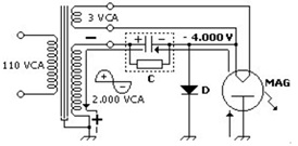
The Magnetron tube is the basic component of microwave ovens. This tube and the high-voltage transformer are the two most expensive parts of the set. A substantial part of the maintenance cases is related to problems with the Magnetron, which symptomatically raise the repair costs. It’s interesting that the tube itself seldom have problems. It simply wears out, although it is necessary too much time for this. Even the heater barely renders open. The most frequent problem is in the connection to the heater. The heater voltage is usually 3 Volts, supplied from an exclusive secondary winding of the high-voltage transformer. Combined with this 3 Volt there is a superimposition of a 4 kV voltage developed in the voltage doubler associated with the high-voltage transformer. This 4 kV voltage (not exactly DC, is pulsating with different voltage levels of same polarity) is the principal supply for the tube, responsible for generation of the microwave oscillation that produces the cooking temperature. Remembering that the heater also actuates as the cathode of the Magnetron.
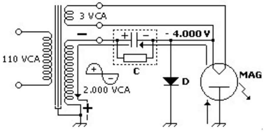
Mechanically, the 3 Volt are connected to the tube through a special integrated connector – the white plastic connector shown in the first picture below. To gain access to the internal part of the connector it is necessary to detach the square cover.
The ohmic resistance of the heater is too low, to such an extent that a measure with the ohmmeter in the X1 scale can be confused with a short-circuit.
This connector is one weak point of the Magnetron tube. The high-voltage in the point can provoke a voltaic arc that establishes inside the white connector, producing a carbon tracking towards the Magnetron housing, which is at ground potential. This tracking remains established at a low ohmic value, even after the arc quenching with removal of the high-voltage. As a result the tracking is permanently established, with the 4 kV voltage becoming always short-circuited afterwards. A quick check with the ohmmeter is sufficient to show this condition (please see the final comment in the last paragraph of this report). From any of the two heater terminals to the ground the low tracking resistance can be measured. This tracking occurs inside the connector, not always can be seen with the naked eye. Sometimes, it shows a charred black point.
This is a banal and unjustified problem, forcing to the replacement of a component that internally is in a good condition, as the connector is integrated to it.
However, there are two ways to recover the tube. The first one is to replace only the connector, that can be withdrawn from a worn-out tube (low emission, i.e., low output power or even none power). Or, alternatively, to buy it, which cannot be always possible. In the first case, the removal of the failed connector is a little bit hard due to two reasons: the fact that the connections (to the transformer winding side and tube side) are done with spot welding, and not with tin solder, and the support strip is too sturdy . Not using tin solder in these points are probably due to the high temperature in these points, generated from the tube operation. The high temperature can melt the tin solder and eventually melt down the connections. In the further installation of the new connector this issue is recurrent.
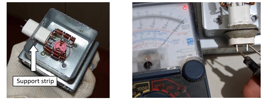
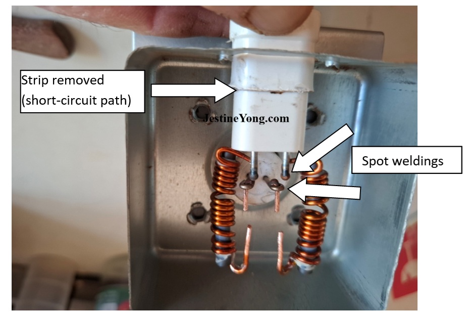
The second way is to repair the connector. The technique in this case is to displace the connector up to a point in which a gap is obtained, sufficiently secure to avoid a voltaic arc to the housing. If the connector is released from the housing and displaced by a few millimeters, the point with the short-circuit is distanced, solving the problem. To do this, it is necessary to cut the two copper wires to the coils (that are RF filter to avoid the 2.4 GHz Magnetron oscillation frequency to reach the residential installation, so causing interferences in other devices) and remove the connector strip. This strip is responsible for acting as a bridge for the voltaic arc and is fixed by 4 rivets to the tube housing. The remotion can be done forcing with a cutter or by drilling with a 3.5 or 4.0 mm drill. The picture below shows the strip already removed. It is not always possible that the strip can be removed in its entirety when not using the drill. It is a sturdy piece, that requires a considerable effort to remove or fold, with the risk of damaging the plastic part of the connector. One possibility is not remove the strip, displacing the connector with the strip in its place. This is a solution that I don´t like, because there is in this case more areas energized, which can give condition to create another voltaic arcs.
The white connector must then be positioned in such a manner to maintain it distanced from the Magnetron housing. Due to this displacement it is necessary to change the connection point between the other side of the filter coils and the heater terminals of the tube. Here a problem arises: the connection of the coils copper wires is done not with normal soldering (tin soldering) but instead with spot welding, as explained above. The solution is to do mechanical connections instead of tin soldering.
The arrangement can be seen in the picture below, that shows the initial relevant details.
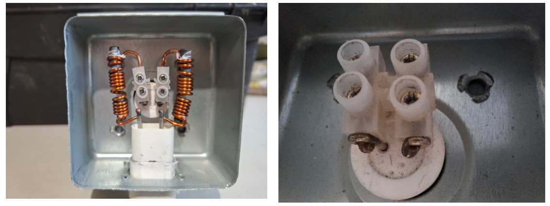
The spacing between the copper wires must be adequate for a stable assembling of a strip connector, avoiding mechanical stresses, as shown in the left picture below. In the right picture the assembling of the strip connector in the tube heater is detailed, before the coils copper wire connections, that will be connected in the upper part.
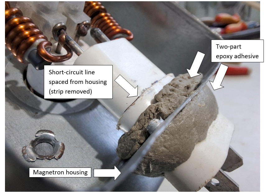
The white connector, already loose, is displaced down in order to ensure adequate spacing between the short-circuit line (line formerly occupied by the strip) and the Magnetron housing. Due to this displacing, the copper wires at the down part of the coils are also distanced – at the same proportion – from the tube heater binding posts. In order to regain this space one turn must be unwinded from each coil. It must be noted that the four copper wire points are with a shiny look due to the scraping done to ensure the suitable electric contact to be carried out – originally the wires are enameled, which gives an electric isolation in the surface, so ensuring that the turns in the coils don´t present short-circuits, which could affect or void the coils inductance. But this enameling doesn´t permit the wire to be soldered (or welded). The scraping removes this enamel layer just in the points to be connected. It must also be noted that the two copper wire tips from the heater must be cut with enough length to allow the fastening with the strip connector to be done, as explained below.
The strip connector can be split cutting it with a utility knife or a knife, in this way giving more mechanical flexibility. This is important due to the coils copper wires rigidity. The use of this type of connector ensures a good mechanical connection, avoiding the use of tin soldering in a point subject to high temperatures.
The next step is to fasten all the set in position. This ensures steadiness to the set, which is important in the moment of jointing the 3 Volt wires from the high-voltage transformer to the white connector. For the fastening I employed a two-part epoxy adhesive. As the white connector is loose, before the cure of the adhesive it must be positioned to align it equally spaced from the Magnetron housing. The picture below shows the result I got.
Before the final adhesive curing is time to do measurings. They are basically two: to check the heater continuity (a value close to zero Ohms, as aforementioned) and to check the isolation between the heater connections to the Magnetron housing. This isolation must present an infinite value, that´s important when one consider we are talking of a voltage near 4 kV. In the case the measures indicate a need for reworking, the not completed adhesive curing facilitate demounting for the necessary corrections.
This process can be considered, to a certain extent, a non-professional work, but it can be justified due to the fact one defective Magnetron can be brought to life, instead of going to the trash. Moreover, the cost for the customer (owner of the microwave oven) can be reduced, being so a difference between throw away not only the Magnetron itself but the whole oven. I used this procedure in a maintenance and the microwave oven is working properly until today.
Another justification is concerned to the planned obsolescence concept, a dishonest practice from the manufacturers. A major part of these manufacturers include this weak point in their products (i.e., installing a low-quality connector to increase the chance to create a voltaic arc), thus reducing deliberately and immorally the lifespan of the products to force frequent replacements. Recovering the Magnetron, as I reported above, is a way to avoid unnecessary expenses and give an adequate response to these dishonest manufacturers.
A final comment concerning microwave ovens: the act of open and carry out repairs in these devices involves the need to have advanced electronics knowledge and experience, to be informed about the typical working of them and to have notion of the (high) risks involved, not only due to the use of a voltage around 4 kV (risk of death) but also by the fact that this voltage remains stored in the circuit even after the device is turned off. Touching in the components, evens with the device turned off, can cause a discharge through the human body, that can be equally fatal.

This article was prepared for you by Henrique Jorge Guimarães Ulbrich from Curitiba, Brazil. Retired telecommunication and electronics technician. Loves electronics, telecommunications, cars, wines and grand children.
Please give a support by clicking on the social buttons below. Your feedback on the post is welcome. Please leave it in the comments.
P.S- If you enjoyed reading this, click here to subscribe to my blog (free subscription). That way, you’ll never miss a post. You can also forward this website link to your friends and colleagues-thanks!
Note: You can read his previous article on Membrane Keypad Retrofit In A Combo Telephone/Radio/Clock Soundesign Model 7541
 (1)Dislikes
 (0)
(0)