
Defective And Discontinued Microcontroller Functions Bypassed In Bang & Olufsen Tape Deck

This has a very long story behind it, but I would make it as brief as possible, without compromising on essential detailing of trouble shooting and rectification done. This belonged to a customer who brought it to me stating that the uController IC TMP8355P-7924 was reported to be defective and it was lying with another technician (also very much known and close to me) for many years. The set was in open condition, i.e., the screws were removed and stored inside.
Why was this brought to me then? I was very ‘notorious’ in making knotty and naughty attempts in electronics impossible and this customer took a chance before deciding to discard it to the dustbin. Needless to mention that the attempt was successful, since this article has the caption announcing the result, as I did not want to keep my friends across the globe in tenterhooks (LOL)like in a horror or detective story!
My first job was to clean the set, which I did using blower and brushes. I dismantled the whole set as there was a lot of dust collection on the boards, which were not reachable otherwise and cleaned it thoroughly.
Before I started the work, I reconnected the boards on the table and powered it up. The relay was chattering and some burning smell with smoke came out from the power supply section. Fortunately, I could fetch its detailed circuit diagram from the net. I studied it fairly well. Then isolated the power supply board. Found the ESR as well as value of the caps way out and replaced these first. Then when I checked, the output voltages were coming. Then checked the power control board and found resistors open and transistors short, source of smoke and burning smell. Replaced the transistors and burnt out resistors looking at the circuit diagram.
Those of you who want to have a clearer look at the schematics, kindly download the service manual using this link:
https://elektrotanya.com/bang-olufsen_beocord-9000.pdf/download.html
Then when I connected, the relay was ok and power supply came on without any problem. The LED indicator of power was also on. The defective IC was sent to me separately. My first duty was to check whether it indeed was defective. So, I looked for any defective components around its circuitry and having found none , placed the IC back on its socket.
None of the control buttons worked and after sometime, the IC was found getting hotter and hotter. So disconnected the power and removed it when it was cool enough. First step was over. The second step was to study the circuit diagram to know what were its functions. Three uController ICs were used, two of similar ICs were slaves. The control board was directly going into IC 3 (another 8055). The main IC was 8049 and these two 8055s were input/output expanders. I measured the voltages available by default (without the defective IC) at the pins Play/Record – 26, Rewind – 25, Fast Forward – 24, Power On – 30 and found these to be held high, i.e, 4.95V Then took print out of all the circuit diagrams, joined it with tapes and kept these on the service table. Took out a separate print of the following function chart:
Several attempts were made to fetch a replacement IC, but in vain. We even contacted the manufacturer and their agents in Delhi. But the product was discontinued. Even Toshiba could not help us. So, my interest to somehow make these basic functions, i.e., power on, play, rewind, fast forward and stop got roused and I continued my study focused on these only. When I used a 1k resistor and grounded the pin 3, the standby got released and the set came on. Then used another 1 k resistor and from the ground and touched the rewind. The motor and solenoid worked, but the rewind wheel did not rotate.
Looked underneath and found that the belt was broken. So, replaced it. Since the belt was in place when I had removed it for cleaning, it would have got cut when the motor started working after a very long gap. When I retried, the rewind wheel rotated. Did the same on Fast-forward after removing the resistor from REW and got the same result. Then when I kept both REW and FF low, the play started working. As the pinch roller was found worn out, I replaced that too. Thus a way to bypass the system was found out. But let me be frank, it took several months and sittings before I could venture to do such things, though it looked simple enough afterwards.
Now next step was to check whether all the other related functions worked, such as headphone amplifier, connection for external amplifier etc. One channel was dead. By inserting two 1K resistors to FF and REW pins from the ground, I set the play on and fed audio signals to Play in/out pins on the board. This board had two Test Points for Left and Right near to the socket of the point where the connector from the head was getting inserted. Then traced the signals in oscilloscope. Both signals were reaching IC101 and 201, HA12038 (Dolby) but it was found missing on IC201 at the output (pin 4). Then I compared the voltages of this IC with the other on the board and made a chart:
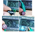
As I found abnormal voltages, I probed the reasons for it by measuring the surrounding components. Found one electrolytic capacitor dry and completely out at pin 2. So, checked a few other capacitors in the boards elsewhere too and found that ESRs were out of range of many caps. Before I delved into my ever time hobby of replacing all electrolytic capacitors, which I always enjoyed to do, I replaced just this capacitor, and switched on the set. Now the signals were reaching both sides as all voltages became normal on this IC then. Just see, one cap can fool us and take us for a ride, if we are ignorant of the methods to be employed and are not equipped with minimum trouble shooting tools! Now that the set was working, though without any quality of audio output, and further that I was confident I could make the play work by using 555 relay on/off system for each function, I went ahead and replaced all the electrolytic capacitors on the boards and retouched the soldering points wherever it looked weak. Cleaned all the boards thoroughly. Just see a few of the readings of the caps. Around 60 to 70% of the electrolytic caps were bad:
By this time, I had started refitting the boards back to its place one by one, for the sake of ease in trouble shooting. Moreover, this unit had boards fit on both the bottom and top cover and it could be kept open by removing the appropriate covers to view the PCBS from both sides. Very good system indeed! (Please see pictures from 4th at beginning of this article) I also noticed fungus formation in connectors and the wires were damaged at the pins inside the sockets. So, removed the pins, cleaned it up, soldered jumper wires on it to extend it outside and reinserted the pins into its sockets in the same order as it was before. Then soldered the inter connecting wires taking care of the positions. The following pictures are just as representations only, as I did the same for a few others too. Two of the shielded wires, one coming from power supply board to amplifier board (carrying common ground, positive and negative supply of 15V each) and another from amp board to headphone socket were found hardened and getting broken easily. So, replaced these two wires too!
Then when I checked, the audio quality was really superb from a cassette that I was tempted to request the owner customer to part this unit for a pay!
Anyhow, next step was to use the 555 relay timer boards that I purchase keeping its use this way. I downloaded the following circuit diagram and assembled a 555 on breadboard and tried. It worked very well. (ON-OFF Switch circuit using a 555 timer (PCB) – Electronics Area)
In the following board that I bought, which was a timer, there was a timing adjustable trimmer, which was not needed for functions such as Play, FF and REW. Out of the five boards bought, only two were working and three were defective. In order to troubleshoot the board, I removed one SMD 555 and checked the connections. Pins 2 and six were linked together and routed through the trimmer, the other end of which was going to ground.
I removed the trimmer (before final assembly for on/off) scraped the inter connection between pin 2 and six of 555, and also that of six from the trimmer. Re-fixed the 555, by which time I found out that the reason for failure of the three boards was due to open SMD LED connected to the output pin 6. Replaced the SMD LEDs and all the three boards worked very well when checked. Then lifted the pin two of 555 from the board, to make it isolated. Connected one 2.2Meg resistor from the positive. Then connected another 2.2Meg resistor from ground to pin 6. Then when I tried touching the negative to pin 2, it got on and when I touched positive to pin 6, it switched off. Made ready two more boards also similarly.
First I fixed a timer relay board (let us call this board as number 1) without any modifications, adjusting it to 15 seconds to short pin 30 to ground through a 2.2K resistor (we may have to make the resistance lower by turning the adjusting screw to make the delay time shorter and vice versa). I used the space of the vacant IC and fixed the relay there and wired it such that when the relay gets on, it shorts pin 30 of vacant IC1 socket to ground through the resistor. The bottom of the board was stuck with a thick cardboard in order to keep the PCB side isolated. (Did same on all boards)
Now the next task was studying the key board to wire the on/off switch boards. The tasks to be accomplished were: Play should work when play switch is operated, but other functions such as FF and REW should not work. Same applied to FF and REW too. In short, when one function is working, the other two should not work. We have single change over relays already fixed in the board. In order to enable play and disable FF and REW simultaneously, I removed relay from one board and used a two change over relay in its place:
Then placed the three relays, one i(let us call this board as number 2) inside the vacant place between the key board and uControl PCB (you can see that in the picture of placement of delayed switch on, another (let us call this board as number 3) on the power supply board and another one (let us call this board as number 4) in the crevice behind the mains transformer. Connected a 12V regulator IC 7812 to 15V supply, and placed it in another crevice found near the power supply board. All fixing was done by using either tags and/or Fevibond (rubber compound) adhesive. Positive and negative wiring was done for all the boards. As each board drew only around 40mA, 7812 could manage the loads. The lack of adequate space for placement of relay boards prevented me from adding more functions such as standby, return etc. Since there were many interconnecting cables between top cover and bottom cover, due to placement of various boards, there were limitations. It will look awkward and spoil the aesthetic look of this wonderful set, if we fix anything externally. I could not even provide a motor off when tape gets over, as the hall sensors were defective. So, I was forced to contain my thrust to activate more functions.
Stripped the key board off (slid the bottom plate out, peeled off the key switch holding sheet, making sure the keys are in its place) and made a chart for the ten outputs from the key board.
In the chart above, ‘inner’ denotes the point on which the metal membrane touches when pressed and the ‘outer’ means the area where the metal membrane stays in contact constantly. In order to enable stop, as we already know, the relays should be switched off by applying positive to pin six of the 555. So, as you can see from the chart above, the stop button outer is going to 8th wire whereas the inner is shared with REW and Standby. Though we do not use standby, sharing with REW will short the positive to ground, as one of the pins of stop will be going to positive whereas the outer of Play, REW and FF are to be wired to ground. The outer of FF, Play and REW goes to pin 10, which makes things easy as it can be grounded. So, I scraped the inner connection of stop and rewired it to pin 7. Then kept all other wires bent, isolated and taped on the other side of the outer wire. Now, I had stop button isolated, and I connected its outer to positive supply (wire 8) and the inner (wire 7) to commonly wired pin 6 of all relays.
Now the task was to wire the relays such that when play button is pressed, its relay should get on, and same way the FF and REW. So, I connected the common outer of all these three buttons to ground. Then inner of play button through its wire number 5 (Please see excel chart marked in Blue) to its allotted board No.2, pin two of its IC 555, which had 2-change over relay in it. So, when play button is pressed, the pin 2 of board No.2 will get negative supply to switch on so as to ground pins 24 and 25 of vacant IC1 socket to ground through 1K resistors. The poles of this two change over relay were connected to ground to enable ground available to its NC (short form for normally closed) pins when not in use. Out of the two two NO (short form for Normally Open) pins one was connected to NO pin of relay in board 3 and another to NO pin of relay in Board 4. Thus these two pins will be held low to activate play in tape mechanism. To explain functionally, when play button is pressed, the pin 2 of 555 in board 2 gets on because of a negative charge, pulling the grounded poles from NC contacts to NO contacts, thereby pulling the pins of 24 and 25 of IC1 to low. Hope I am clear. I am including a rough drawing later to explain the flow. Then wired the inner of Wire numbers 4 and 6 from its buttons (Please see excel chart – marked in Yellow and Green) to REW and FF boards Nos. 3 and 4. Only change that I did from the relay connection side was connecting pole of board 3 (REW) to NC side of board 2 (Play). This makes it possible to disconnect availability of ground to REW, when play is in operation. Because when that relay operates, the poles disconnect from its NC side. Then wired the pole of board 4 (FF) to NC of board 3 (REW). So when REW is in operation, FF will not get ground. The next board No.5 was modified to remove the timer and operate instantly for use as STOP. The 12V supply for its operation was routed through the stop button so that when it is pressed the relay will supply positive to pin six of board numbers 2, 3 and 4 (Play, REW and FF). The user should invariably press stop after all these three functions to disable the relays. But no damage will ever happen even if it is not done. . I am giving below picture of a crude drawing that I tried to make after a few failed attempts and wasting paper (Environmentalists and Tree lovers to pardon me!) (I had to use Paint to cover some mistakes which I had scribbled out)
After all connections were over, I used the functions and everything worked very well, which made me very happy, having employed some new ideas and methods to make the discarded device work! Reassembled the set and closed the case.
Some of you might ask why I opted for relay on/off instead of going for mosfet or transistor circuit, which could do the same function. Well, the reasons are that first of all I wanted to isolate the main circuit from its control circuit, which is possible by relay operation. Secondly, if any failure takes place, that can cause damage to control circuit and other circuits of the tape deck. Thirdly, I need to either hunt for a suitable circuit and modify it to suit the power supply in this or design one, both of which are cumbersome and my mind is not trained for such innovative designs; at least as of now. Perhaps I might try and do such alternatives in a couple of other uController failed amplifiers lying with me for a very long time, as the customers have more or less abandoned it!
Well, don’t worry, I will not forget! Here is the picture of the components replaced:
Satisfaction in multiples with full intensity jumped into its collection bag with a bang! Thus curtain was drawn on this long pending issue, which could be made possible during the locked down period. As the inflow of sets stopped, I concentrated in clearing up the backlogs. There are a few more to be cleared like this. Until then, a good-bye!
This article was prepared for you by Parasuraman Subramanian from India. He is 72 years old and has more than 30 years’ experience in handling antique equipment like Valve Radio, Amps, Reel Tape Recorders and currently studying latest tech-classes conducted by Kerala State Electronics Technicians’ Association. He has done graduation in BBA degree, private diploma in Radio Engineering and retired as MD of a USA company. Presently working as Consultant to Hospital and other institutions.
Please give a support by clicking on the social buttons below. Your feedback on the post is welcome. Please leave it in the comments.
P.S-If you enjoyed reading this, click here to subscribe to my blog (free subscription). That way, you’ll never miss a post. You can also forward this website link to your friends and colleagues-thanks!
You may check on his previous article on Marantz Amplifier Repair
 (51)Dislikes
 (1)
(1)
30 Comments
Leave a Reply


Menahem Yachad
June 14, 2021 at 3:24 pm
Outstanding work! Well done!
Parasuraman S
June 14, 2021 at 4:40 pm
Many thanks for your comments!
Mario
June 14, 2021 at 3:30 pm
It's a *fantastic* repair. Also your customer should realize that he has a FRIEND over than a technician! Here in Italy, very few people would have appreciated such an incredible adventure ó patience, ingenuity and care for this repair, which to be honest i think it's value is inestimable! Congratulations and... I would like to know a person like you in person! FANTASTIC ACHIEVEMENT!
Parasuraman S
June 14, 2021 at 4:41 pm
Vow! Packed full of accolades! Many thanks for your comments! Very encouraging!
moshe jacobson
June 14, 2021 at 4:56 pm
That was an outstanding...no it was an exemplary....undertaking...absolutely amazing!
Parasuraman S
June 14, 2021 at 7:40 pm
Many thanks for your comments!
cheis
June 14, 2021 at 5:11 pm
Brilliant Repair and explanation to boot
Parasuraman S
June 14, 2021 at 7:41 pm
Many thanks for your comments!
Albert van Bemmelen
June 14, 2021 at 8:57 pm
You give new life to good old proven methods and new life to the old 555 chip!
But I hope you are not too disappointed if I tell you that the TMS 8355P still is available if that is the chip you searched for?! See here at eBay as one of the options. They are not cheap but in case it is the right replacement chip no doubt would have saved you a great amount of work and time too. But a great repair it was!
Albert van Bemmelen
June 14, 2021 at 9:05 pm
But if it is a by Bang Olufsen pre-programmed ROM according to this datasheet instead a microcontroller chip: it of course won't work without the original ROM firmware.
Parasuraman S
June 15, 2021 at 11:43 am
Yes, very true!
Parasuraman Subramanian
June 15, 2021 at 12:44 am
Many thanks. The problem was as you yourself have mentioned below.
Albert van Bemmelen
June 15, 2021 at 1:16 pm
I still wonder how the previous repair engineer and your close friend made the assumption that the TMP ROM chip was defect and why he thought it was a microcontroller? And in that relation how he thought that the just one microntroller still was okay? Did he maybe have a second still working device to compare the results with to check this? He most likely had just replaced the original microcontroller with another good controller he had to check this, because you normally can't simply check these in any universal programmer.
Parasuraman S
June 15, 2021 at 3:17 pm
The first symptom was that none of the controls were working. The IC was getting hotter than the other similar one. He never had a circuit diagram nor did he have an oscilloscope. (Poor guy died later on due to cancer!) He too did the basic things required to confirm more or less that this slave IC was defective. The unfortunate thing was neither of these parts were available, nor was there a similar IC used equipment in stock. Many thanks for the time you are spending to ponder over various aspects of this case. Shows how involved you are and make people like us to be more alert in many angles!
Tom Kuriakose
June 14, 2021 at 9:05 pm
very informative, thanks .
Parasuraman Subramanian
June 15, 2021 at 12:45 am
Many thanks for your comments!
Andrew F. Ali
June 15, 2021 at 3:23 am
Excellent work!!!
Parasuraman S
June 15, 2021 at 11:42 am
Many thanks for your comments!
Paris Azis
June 15, 2021 at 4:12 am
This was a remarkable attempt of equipment survival! Good job, Parasuraman!
Parasuraman S
June 15, 2021 at 11:42 am
Many thanks for your comments!
Suranga Bandara
June 15, 2021 at 8:45 am
Good Repair Job..
Mr,
Audio Expert.
Parasuraman S
June 15, 2021 at 3:10 pm
Many thanks, Suranga!
Waleed Rishmawi
June 15, 2021 at 1:33 pm
a provided schematics that make things easier in the repair business. a well done repair job my friend. have a blessed day
Parasuraman S
June 15, 2021 at 3:10 pm
Many thanks, dear friend!
Yogesh Panchal
June 15, 2021 at 2:37 pm
Good job! Sir,
It need to much patience to revive this type of equipment.
Parasuraman Subramanian
June 15, 2021 at 9:11 pm
Many thanks!
Lee
June 15, 2021 at 2:44 pm
I think you could of gotten all the functions going if you had used a picaxe controller and wrote the program to do all the functions. https://picaxe.com/
As usual you go above the call of duty with this repair.
Parasuraman Subramanian
June 15, 2021 at 9:15 pm
Many thanks for the tips and comments! Inserting another unit and interfacing with the other two ICs cannot be done without getting the original codes. Anyhow, I am not familiar with such programming either! Shall see the link and try to learn!
Haneesh P
September 5, 2021 at 1:15 pm
You are truly a genius in all aspects, your patience is remarkable, I learned a lot from our articles, not too many such geniuses are keen to share their knowledge, its these kind of out of the box thoughts saves us.
Thank you and keep us this great work.
May I contact you for any questions when end up in such dead ends?
Regards,
Haneesh P
Kozhikode
Parasuraman S
March 3, 2022 at 6:53 pm
Many thanks for your comments. You can get in touch with Mr.Jestine Yong, who would provide your my contact details. As we stay in the same state, this would make intercommunication better.