
FARFISA ART-482/1 door entry intercom repair
In the building where I live, among the various installed systems therein, there is a Farfisa door entry intercom. The system was put in operation from the beginning of the life of this building, namely it exists for 23 years up to now. At the end of last May there was a system failure. Nothing was working. No picture of the entry door camera, no sound and worse than anything else no electrical control on the entry door opening mechanism.
The building manager, knowing about my profession of course, asked me to take a look on it. The case was really difficult due to the fact that the system was already very old and when the building manager asked the official service center of this company for help, they informed him that the system was characterized as obsolete and therefore it was beyond any technical support any longer.
I answered the manager that I will see what is going on with it and try to repair it. The system has its PSU installed separately in the basement of the building. From there leaves all the cabling to the front of the entry door where the camera box is installed, along with the intercom audio amplifier and the panel with the calling buttons which energize each buzzer of each respective apartment of the building. Moreover this PSU controls the distribution of the video-audio signals coming from the camera box towards each of the internally installed video monitor- handset located in each apartment. Of course the system is already very old and its video monitors are based upon 5” B/W CRT displays technology. Nevertheless its picture quality was still very good.
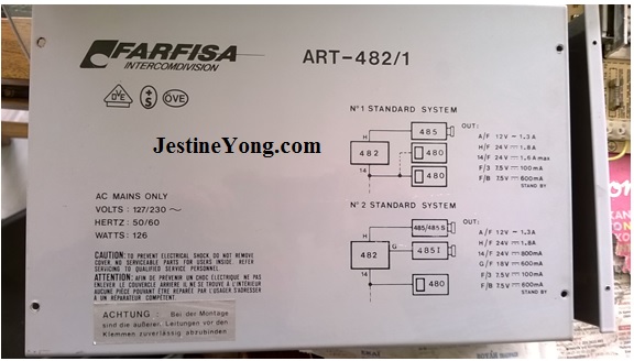
You can see the PSU box below:
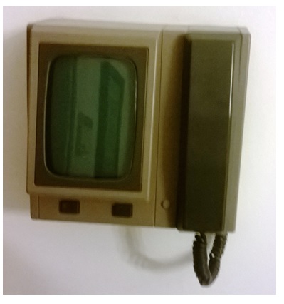
And the internal video monitor-handset below:
Well, having myself seen the symptom of this failure it was easy to find out where the trouble was. No doubt it was a PSU failure.
So, I went to the basement of the building to check it. In that place there was a strange smell like burned paper, dispersed all over the area. Very soon I realized that this smell was coming from the PSU box…
I opened the front cover of it and verified that the smell source was the power transformer. Bad news therefore…Next, checking the fuses of the PCB, I saw first one of them wrapped with copper wire, which already was melted. This fuse is rated at 1,6A and is a slow-blow one. Upon pressing the “open the door” button of the internal video monitor units, it supplies the electromagnetic lock of the entry door of the building with 12V A.C, which in turn pulls the lock blocking lever, releasing the lock and allowing thus access on door opening.
Apart from that above, one of the (two) transformer primary protection fuses was also blown.
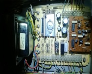
You can see below the internal parts of the unit. The two missing fuses are: just above the big 5V regulator the first one, rated 1,6A and used for the protection of the electromagnetic mechanism of the entry door along with the secondary winding of 12V A.C of the power transformer which feeds it. This secondary winding is connected with the two grey color cables in the PCB. The second one, rated 1A, protects the one half of the primary winding and is located just below that regulator, at its left corner. Also the one at its right side has the same rating as the previous one and protects the second half of the primary winding. There are no more fuses on this PCB.

For better view of the first fuse’s place you can see the picture below:
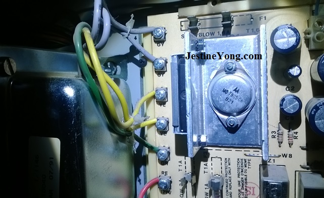
And for better view of the second fuse’s place you can see the picture below:
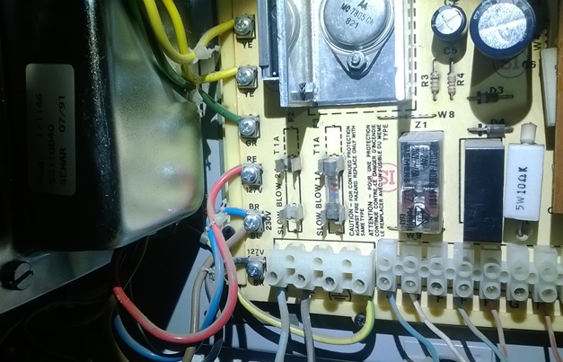
Furthermore, with blue-red is shown the one half of the primary winding, while with blue-brown is the second one. Each one is rated at 127V A.C and the brown-blue connection is their middle connection which is not connected to anywhere else, as the two half primaries are connected in series in order to meet the European voltage standard of 230V. In a 110V system they would be connected in parallel. This flexibility makes the use of this unit universal in terms of utility voltage.
Note as well that the manufacturer took in account the fact that this transformer is intended to work round the clock and therefore they made its primary capable to withstand 2×127=254V instead of the nominal one of 230V. The net practical result of this provision is that the transformer is working at a much lower than its normal operating temperature while being under its nominal load. This results in turn in extended longevity of the transformer.
The yellow-yellow-green secondary winding unfortunately had no voltage information on neither the PCB or on the transformer’s body. Now the picture was quite clear, not even needing any fuse replacement and retest the unit afterwards…I removed the entire unit for repair.
First of all, I tested the power transformer in unloaded condition, using again the well known lamp trick. I connected in series with the primary windings a 230V/40W test lamp. Upon powering the transformer the lamp was on with full brightness as I expected…
Now what? I already knew from the building manager himself that the device had no technical support any longer from the official service center and I hadn’t all the necessary information about voltages and currents of the transformer’s windings in order for me to order a new one with these characteristics from local transformer manufacturers…
On the other hand the information about replacing the entire system with a new one was that it would cost around 4000€ (material and labor, for new equipment of equal quality). Under the current circumstances…no way for such a replacement. So, I had no other choice but to open the transformer and assess the vital information about its parameters by measuring the count of turns of each winding and the wire diameter of it as well…
The transformer is shown below:
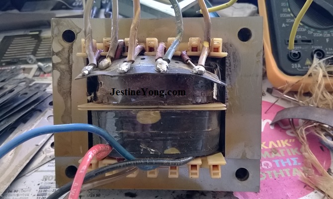
In order to make the long story short, this took me one full Saturday in working hours. The 12V secondary winding was melted and I could hardly remove it from the bobbin. Dismantling the transformer’s core was also impossible as its impregnated laminations were toasted and stuck with each other. The odyssey had begun. I started removing and counting the turns one by one until I had the full drawing of the transformer windings available along with their wire diameters. Then I performed all the necessary calculations to verify that the voltages and currents I assessed represent the original parameters of this transformer. After this verification, I ordered a new transformer. Meanwhile the static tests I performed in the rest of the discrete circuit components didn’t show any defective component. This left the question “why this transformer’s 12V winding was found melted” an open issue (apart from the stupid heavy bridging of the fuse with copper wire by whomever did that).
After some days I had the new transformer in hand. It had almost the same base with the original and so the mechanical rework I had to do was easy. Only two new holes in the chassis. Then, I reassembled the entire unit and reinstalled it in the basement.
Upon powering it, the 12V A.C fuse was instantly blown. So that open question I had before, came to its answer. I removed the burned fuse from its holder and then ran an Ohms test in the remaining circuit. The result of it was zero Ohms! There was a short circuit somewhere in the entry door locking circuit.
I went at the entry door and dismantled the locking mechanism. I performed a new Ohms test of the electromagnets’ windings resistance. Zero Ohms! The culprit was found. I opened the assembly just to satisfy my curiosity. The (two) internal electromagnet windings were melted.
I went at once to buy a new lock from a nearby shop and replaced the old one. Then I performed a new power up of the PSU after replacing the lock fuse again. All perfect. I performed all the voltage tests and found them as expected. I verified that the calling function to each one of the apartments was functioning properly and asked the people there to check and report to me if they had any problem with the system. Everything proved to be in order.
Then I left the front cover of the PSU open for two hours more and then I checked the transformer’s core temperature. This was also fine. No feeling of overheating by touching it. Next, I closed the unit putting its front cover back in its place. The repair was over.
All these four months passed from the date of its repair, the entire installation operates in proper order. And I am very happy using it many times every day, remembering the little odyssey I suffered during its repair.
Nevertheless it was really worth it.

This article was prepared for you by Paris Azis from Athens-Greece. He is 59 years old and has more than 30 years’ experience in electronics repairs, both in consumer and industrial electronics. He started as a hobbyist at the age of 12 years and ended his professional carrier as a senior electronics technician. He has been a specialist in the entire range of consumer electronics repairs (: valve radio and BW TV receivers, transistorized color CRT TV, audio amps, reel and cassette tape recorders, telephone answering and telefax devices, electric irons, MW cooking devices e.t.c) working in his early stages at the official service departments of National-Panasonic first and JVC afterwards, at their premises in Athens.
Then he joined the telecoms industry, working for 20 years as field supporting technician in the sector of DMRs (: Digital Microwave Radio transmission stations), ending his carrier with this subject. Now he is a hobbyist again!
Please give a support by clicking on the social buttons below. Your feedback on the post is welcome. Please leave it in the comments.
P.S- If you enjoyed reading this, click here to subscribe to my blog (free subscription). That way, you’ll never miss a post. You can also forward this website link to your friends and colleagues-thanks!
Note: You can check out his previous repair article below:
https://www.jestineyong.com/konig-pa-10000-amplifier-repair/
 (105)Dislikes
 (0)
(0)
36 Comments
Leave a Reply


Bernie Scott
October 7, 2015 at 9:17 pm
Great repair job...and very time consuming to be sure.....sometimes repairs can take a while.......keep up the good work....
Paris Azis
October 8, 2015 at 12:00 am
Hello Bernie
Thank you for your warm comment and yes, some times when a repair seems to be the only effective solution, time is no longer a problem.
Best Regards
Albert van Bemmelen
October 8, 2015 at 12:44 am
Quite an adventure you undertook! Repairing bad Transformers is not my cup of Tea, but you managed to figure out what the specification of the old one was. By dismantling the old transformer secundary Windings. To be able to replace it by a new one with the same specifications. Strange that after only 23 years no one had a circuit plan or schematic of the Door Entry System. The system in my Flat is almost that old and still worked and was only replaced by a new one recently because it has a small Texas Instruments controlled chip inside to safe on standby power costs. But I wonder, couldn't you just have found the information you needed by looking at the electronic parts and their maximum voltages? Or gotten the info from the size of the Transformer Core instead all the trouble you took to dismantle the old smellie secundary Winding? No doubt well done!
Paris Azis
October 8, 2015 at 5:41 pm
Hi Albert
I really couldn’t find any info about this transformer. The only indications I had about it were the nominal voltage of each half-primary winding and the voltage (12V) of that secondary winding used for the door lock. The wattage parameter was of course easy to obtain by a simple assessment of the core area section, given in cm2. (It finally resulted in a 150 Watts core). Therefore a lot of information was still missing. For example I had no idea about the currents of the windings. How could I order a new one under the circumstances?
I was then forced to do what I did in order to obtain accurate information about those windings. Of course I worked with the well known formula of: N1/U1 = N2/U2 etc…The current ratings are taken from tables giving data about enamel transformer wire, based on their diameter, which I measured with a micrometer I have…
Apart from that, I must confess to you that I love the job of rewinding just anything! Strange? I don’t know, but it is a work I do with great pleasure, especially when it comes to transformers, just because they are a basic part of the power electronics object with which I am long ago in love and as a result they attract me strongly.
Needless to tell you that I have rewound every case the professionals refused to rewind, just to save the apparatus…
No matter if one calls this an obsession or madness, I don’t really care. It is pure love to me and I really enjoy the survival of the otherwise junk equipment…
Best Regards
Robert Calk
October 8, 2015 at 11:07 pm
Hi Paris,
I to love to take transformers apart. I bought a bunch of different sized enamel wire so if I can't find a replacement pretty cheap, I'll rewind it myself. Those small switch-mode ones with the plastic bobbins are the hardest, it seems. I always break a piece of it. I've tried different ways of breaking loose the glue they use to put them together, but it is some really tough glue.
Paris Azis
October 10, 2015 at 2:13 am
Robert, switch mode transformers’ rewinding is much more difficut task than it seems to be.
Anyway, try this method and you will succeed without breaking the (sensitive in impacts) ferrites.
All you need to dismantle a used ferrite-core transformer is to heat it up highly but gently. I will explain the two terms immediately.
“Highly” means heating it to such a level (using heating gun) that the two halves of the core can be separated (because the gluing effect has been neutralized by heat).
“Gently” means a) not to toast the ferrite core, because its original permeability will be lost forever and b) your pulling force in order to separate those halves of the core must be accurately controlled, as the heated core is prone to break much more easily.
I wish you success in your next rewinding (for which I am sure in advance)!
Best Regards
Albert van Bemmelen
October 9, 2015 at 12:18 am
I fully understand your great drive Paris! And thanks for explaining. But it probably also means that you had done these difficult tasks succesfully very often before. And it must have given great satisfaction every time something that probably no one else could have fixed was saved by you only. (If you are ever in the neighbourhood please drop by, I have also a few bad transformers that you undoubtably could fix.). No, but serious I was just thinking that you had everything you needed to know from indeed the Transformer Core Size. The Wire thickness used, The Fuses that were used on Board. And the Voltages could be destilled from the used electrolytes and out of the minimum voltages necessary for the Voltage Stabilizer and other parts on board. And from the Resistance of the Load you could also define the needed current and so the Power Dissipation. (DC => Voltage = Current x R). You also could have tried it by connecting another adjustable external DC Power supply. I guess there was no identical building with the same Door Entry Electronics either? I myself would have done anything to prevent the neccessity to dismantle an old useless Transformer. I take it you gave the Buildingmaster the schematics of Transformer circuit? On Instructables there recently was someone who also did incredible things like you with old Microwave transformers that secundary were rewinded to be used as Welding transformers. Maybe it is a great idea if your next article would be about explaining the principles of making a new transformer? It is something that only very few of us master. Just thinking.
Paris Azis
October 10, 2015 at 1:51 am
Hi Albert
If I start answering you from the easiest part, this would be to write an article about a (linear) low power transformer. I have also seen these modifications on M/W oven transformers which are then used as welding machines. No problem with that. It is only a matter of calculations. In the same way work some “gun” type soldering irons, which are nothing more than a simple application of a toroidal core transformer. I own one Weller unit of this type, rated at 120 Watts, which I bought about 40 years ago…It heats really instantly, but I use it rarely because it is not temperature controlled and not suitable at all for modern electronics due to its high power. On the other hand it overheats with prolonged use, and this is absolutely logical as it is not intended for such use.
Now, about the transformer…I understand what you say. There is logic in it, but the needed accuracy in fixed parameters is still missing. This is because an assessment of the working voltage of a transformer’s winding based only on the voltage rating of the filter capacitor is not a safe basis at all. Especially if someone else had worked on the device and for any reason upgraded their voltage rating. Next to that, the case gets more complicated when multiple secondaries are used, as happened in my case. Your reference about the stabilizer also leads in deep waters as this voltage was produced from the 2x15 V a.c. winding, along with all the rest of the d.c voltages shown in the external case of this PSU…
Of course it was much easier to me to count turns, instead of trying to analyze the entire electronic circuit in order to just estimate the parameters of the windings…
There are some more (open) questions. How could I find another building with the same equipment? How could I assess the load resistance of the system? This formula you refer to is used practically for d.c, but my load was not Ohmic. It was a set of similar devices. “Cos phi” is always present in such cases. Even for the 12V winding alone, its rating (due to its diameter) was 3,5A approximately, while its protection fuse was rated 1,6A. What could I take as a safe base? 1,6A?
Thus if we sum up all of these factors, I believe that the safest way was only to do exactly what I did. I think that anything else is nothing but approximations. Not an assessment “per se”.
And yes I did this so many times in the past, that I am used to it and it gives me pleasure. I wish I could fix your transformers as well, but you live a little bit far from my neighbourhood!
I hope that my reasoning has finally convinced you.
My Greetings to you
Albert van Bemmelen
October 10, 2015 at 6:11 pm
Thanks again Paris for your very informative answer! And sorry if my previous post seemed a bit long. I completely understand why you had to do it in the way you did solve it. But I myself never had the confidence to try and repair or destillate the old transformer the way you did it.
And I noticed that also Robert is more experienced in the field of making a new transformer. But I guess the laminated core (to reduce the field energy losses in the core which produce heat) never can be opened afterwards like he mentioned earlier? Did you however manage to find a primary transformer core that still was suitable up to 254 Volt AC? Thanks !
Albert van Bemmelen
October 10, 2015 at 6:17 pm
PS: About mentioning the Fuse being 1.6A while the Transformer calculated to be 3.5A is no problem I guess? Because it is always better to have a larger transformer to compensate for any peak currents. So you still could have used that information while looking for a suitable replacement transformer?
Paris Azis
October 11, 2015 at 12:52 am
Hi Albert
First of all you don’t need to feel sorry about anything. Feel free instead to express your opinion or put your questions even though they are lengthy.
Apart from that, any transformer end especially the classic one with the laminated core can be dismantled and repaired or modified to give a different output than the original. There is no problem at all with excessive eddy current losses as compared to the original magnitude of them, as long as the core laminations are tightly hold together, as they originally were. This is the reason that usually the cores are impregnated with a special substance which works both as insulating and at the same time as gluing material.
As regards the specific transformer I ordered, I had given the constructor beforehand the exact info about nominal voltages and currents of the windings at 254V input voltage. Therefore I practically received an exact copy of the original.
And yes, Robert seems to be very familiar with this task…(And I like that)!
Now about the fuse of the 12V winding: this not only is not a problem at all, but it also means that the winding can tolerate much higher current. Practically the fuse puts the upper current limit, but the winding works in a more relaxing mode in terms of temperature development on it.
You know, as I keep on answering you I realize that you were right proposing me to write a relevant article. I have the feeling that more questions will pop-up in your mind as I go on with it…So, I guess I’ll try to organize it so that you along with anyone else interested in this topic can have a clear picture of it.
Best Regards
Albert van Bemmelen
October 11, 2015 at 5:17 pm
Thanks Paris! You make modifying or disassembling an old Lineair - as you called the 50/60 Hz - transformers, sounding very easy! Most big square transformers I know are even if they are pre-heated almost impssible to seperate because of the thin laminated glued together plates. And of course because of the glued Windings around them. As you say the classic one with the laminated core can be dismantled and repaired or modified to give a different output than the original. That would most likely be the case if I would try such an enterprise (LOL). It is more difficult to make it identical to the original I guess. I don't know of any examples of people who documented this dissasembling a transformer core part into clear detail. And doing this heating a glued core until it is open thing won't be very healthy either. So I wouldn't want you to feel obligated to undertake such a task on my account! So please stay healthy and do the less impossible repairs. Thanks!
Paris Azis
October 13, 2015 at 1:16 am
Hello Albert
If you dismantle some of them you will get the needed experience and things will be much easier thereafter. Of course is a difficult task, but nevertheless worth to know it and use this knowledge especially for repairing costly (or vintage) equipment.
The laminations, although it seems impossible to remove them, can be removed. The problem is to remove the first two or three of them and then the core is not so tight and makes things easier. On the other hand, not all the cores are impregnated. In many of them you will see only the laminations without any enamel substance gluing them.
The usual structure of the core is using the so called E and I laminations. Anyway I will try to present all of it in a new article.
For the time being just keep in mind that nothing is impossible. There are alternatives in most of the cases (talking about technical matters of course).
No, it is not difficult to make a transformer as it was before its failure. It is more difficult to make modifications instead.
The heating of the core is mostly applicable to switching transformers as they are always glued. Another inherent difficulty with them is to secure the air gap if needed, at the reassembly phase. I have never heated a classic core in order to dismantle it.
And yes, during heating there is always a bad smell present and you need to work in a very good ventilated environment, most preferably in open space.
Finally I will try to follow your advice, for which I give you my thanks as well.
Best Regards
Robert Calk
October 8, 2015 at 2:04 am
Excellent repair, Paris! I hope you got a month of rent free. Of course, a new system would use less power than that old one.
Paris Azis
October 8, 2015 at 5:50 pm
Thank you Robert. You are right about the operational costs but “what is costs in front of beauty”? (This is a paraphrase of another Greek wise-saying. I replaced with “costs” the word “pain”. It refers to women that suffer from permanent and extensive diet in order to remain beautiful.
Well, I suffer the same in order to bring dead equipment back in life (although I hate diets too much)!!
Best Regards
Robert Calk
October 8, 2015 at 11:14 pm
Most men don't think skinny women are beautiful, at least here in the USA. I have always preferred women that have some meat on them. Back in the old days, people thought that skinny people had something wrong with them.
Paris Azis
October 10, 2015 at 1:56 am
Robert Calk, because of this answer alone, I consider you as one of my best friends!
This is both an official and public statement!
Man you deserve it!
Best Regards
Albert van Bemmelen
October 11, 2015 at 6:13 pm
You Guys are Funny! Not everything is about Electronics!
Don't let me interrupt your conversations (LOL).
Cheers.
Paris Azis
October 12, 2015 at 4:26 am
Yes Albert “Der Grosse”.
Not everything is about electronics in life…And it seems that I and Robert have something more in common than only liking to dismantle burned transformers and rewind them…Don’t you agree? (You don’t interrupt at all anyway)…
I have all the calculations for the Farfisa transformer ready in a new article. I will send it tomorrow to Jestine, after a final review. I hope that it will answer the questions you have so far.
Next I will prepare another one including all what is needed about the topic. And it will be dedicated to you in order for you to have all the answers you need about the topic!
Greetings to you
Albert van Bemmelen
October 12, 2015 at 5:42 pm
No need to hurry dear Paris! Of course I will read it as soon as it gets published.
I think one of the clues will be that the lineair transformer core exists out off two identical halves? At least that sounds a lot easier than dismantling every laminated plate apart. Todays modern transformer cores are toroidal sized. And even those are made by winding machines. Taking apart and reassembling the core with all the glue on it will require some skills and the right equipment I guess? I hope your article will explain how to do the at first almost impossible.
Robert Calk
October 12, 2015 at 9:06 am
Thanks, Paris. I consider you a good friend also.
vas
January 22, 2020 at 12:43 am
I search a schematics of farfisa intercom, that have an "anti-LARSEN" circuit to eliminate antilocale effect between microphone and loudspeaker. Have you? Thanks.
Gary Gemmell
October 8, 2015 at 8:10 am
Great article Paris - I hope you charge high price for such excellent service.$4000 lol
>;o)
Mark
October 8, 2015 at 9:44 am
Well done Paris! Sometimes it is easy to see the result when looking for faults, but much of the diagnosis time can be taken in actually finding the cause of the component failure. You followed a good diagnostic process.
Now.................how much to charge the customer??
Paris Azis
October 9, 2015 at 2:07 am
Hello Mark
Thank you for your positive support. As regards those charges… please see my answer to Gary below…
Well, as I see the job of electronics’ repairs, the major part of it should refer to diagnosis. This is of utmost importance and also is a permanent idea in my mind.
Talking with percentages, I would give the diagnosis part an 85-90% of the repair time and the “surgery” part only 10-15%. As a result, my soldering iron is always out of power until I find a defective component. Then the moment of “surgery” is there. Only then I power it. And right after the removal of that component I turn it off again. The heated, ready to use soldering iron is always a bad temptation for unnecessary “surgeries”…On the other hand the “how to desolder/solder it” is again a tactical part/result of the preceding diagnosis…
Best Regards
Anthony
October 8, 2015 at 9:54 am
Hi Paris, That was a superb effort and the stuff of legend ! Hopefully they will put a statue of you in the town where you live as the man who NEVER gives up on any repair ! An excellent job completed with a fantastic outcome !
Thank you for sharing your electronics experience with us.
Kind Regards
Paris Azis
October 9, 2015 at 2:29 am
Hi Anthony
Thank you for your warm and supporting comment, although you exaggerated about an (intensive be it) attempt of mine!!
Nevertheless I admit that I never give up an attempt to repair something, with two exceptions: a) if I cannot find spare parts to replace the defective ones and b) if I cannot do any modifications using existing material, just because it doesn’t fit the case. But if I do not fall into these two categories, there is no chance to give up. It works like an obsession in my mind. It attracts me just like a magnet does to iron…
Best Regards
Yogesh Panchal
October 8, 2015 at 4:04 pm
Good attempt sir.
Paris Azis
October 9, 2015 at 2:31 am
Thank you Yogesh.
Edd Whatley
October 8, 2015 at 5:29 pm
Sir Paris . . . . .
Complementing Sir Alberts earlier comment. . . . .with your knowing of just the electronics portions supply, as for it being less than the main filter capacitors voltage rating.
Looks like Semar transformere in Italy is still in the transformer business, with now mainly transitioned to SMPS transformers, but still listing mains transformers
from ,5KVA on up to 5KVA.
But with there shift of using bare wire terminals coming out of the potting versus old school wires.
http://www.semar.biz/eng/products/trasf_rete.html
Many-many times I also had to do a tear down like you did, and if still, somewhat working, determining the spec'ing of its
load characteristics of it having ~10% load drop on a PREMIUM heavy duty units.
Or finding later cheap-o's that would spec out at a ~20% drop unloaded/to/loaded.
I quite enjoy still working on equipment of that vintage.
When they built that unit up, they seemed to be rounding up a hodge podge of components, it looks like a July of '91
for that SEMAR power transformer and some old new stock of 21st week of 1988 for your 5 V regulator but resolution precludes dating the units op amps and TTL /or/ CMOS DIPS.
If one were worried about the transformer, a stand alone one just for the door latch use/function might then totally allay that fear.
Any one that has dealings with these systems KNOWS that the unit owner constantly holds down on the button FAR-FAR longer than being neccessary.
If one HAD to solve that system problem they could revert to rectifying to DC supply and a reservoir capacitor and its series semi circitry such that the INITIAL power activation is initiated with an initial STRONG ACTIVATION BURST of their combined power and then it reverts to being just adequate latch holding power, at a much reduced power consumption.
I have that circuitry in my files for its use on power relays, to keep their coils cool and reduce overall power.
Thanks for the memories . . . .
Edd
Paris Azis
October 9, 2015 at 3:21 am
Hello Edd
I know of course that the filter capacitor’s voltage rating gives a quick estimation of the A.C voltage of the winding which feeds the capacitor, but this is only an indicative estimation and not the exact voltage needed for ordering a new transformer. On the other hand, the current info is still missing. That’s why I did what I did.
Well it seems that we have many things in common. I also like vintage equipment repairs and similar tests like you do on transformers in order to calculate their stabilization factors.
I agree with your thought of putting in operation a single 12V transformer just for the door lock, but I am not sure if this would work as a stand alone unit, without the system control to be operative…Perhaps it would be possible to open the entry door, but I don’t know if the calling buttons would be operative in order to open it…
As regards the cause of the transformer defect, although I fully agree with your notice that people normally push the “open the door” button for too long, which heats the transformer more than its normal operating temperature, the circuit is fuse protected for excessive currents. The problem always starts when the fuse is bypassed with copper strands…
Finally I know very well the circuit you describe about relay driving. I had repaired similar circuits many times in the past years, especially when repairing the early video recorders which made extensive use of them at that time. As I remember there was a strong pulse to activate the relay using a capacitor discharge and afterwards there was only the holding current on the electromagnets coil.
You have also brought me sweet memories and therefore I thank you too!
Best Regards
Paris Azis
October 8, 2015 at 6:03 pm
Hi Gary
Given that the economical situation in my country is simply terrible and beyond description, I charged them nothing at all. I asked them only to cover the expenses of this repair resulted from buying the new transformer, some other spare parts I bought just to avoid running here and there at the last moment of the repair procedure and finally my transportation expenses.
What could I charge them, when half of the people living in the building are jobless?...
Best Regards
Robert Calk
October 8, 2015 at 11:27 pm
You're a good man, Paris. I hope that things improve there quickly!
Paris Azis
October 10, 2015 at 2:20 am
Thank you Robert. I hope so myself as well. And as said, “Hope dies last”…
Positive thinking is our only choice…
My Best Regards again
Edd Whatley
October 9, 2015 at 5:19 pm
Sir Paris . . . . . .
Parte Deux . . . . .
Because I totally forgot to make referencing to your top . .initial photo.
Its coverplate data seems to give you all of the power supply data if
additionally you fudge in giving even a wee bit more power overrating.
In viewing that coverplate, I am seeing an Italian product installed in a building in Greece with a label / notation on it in German.
Available resolution precludes my making out EVERY number, exactly, but I seem to be seeing power requirements of :
12V @ 1.3 A
24V @ 1.8 A
24V @ 800 ma
18V @ 400 ma
7.5V @ 100 ma
7.5V @ 600 ma in Standby
And over to the left, the unit is rated at a power level of 126 watts.
From the installation options, the 482 can feed from either one camera or have another camera for another entry/exit in the Standard system 2 hookup.
Since this was quite a pricey installation, how may building units have CRT displays in them, and how many units in your building?
On the wall control unit in apts, is the video automatically warmed up on every ringing of a visitor, or is there a turn on option at the unit.
Since I am seeing two rectangular buttons, one would be for activation of the door solenoid with yet another unknown function for the other.
Also with the referencing of sizing to the handset, and the units ovrall depth, that must use one small mini neck 110 degree kine.
Thats it . . . .
You drove home only what WE read here in the newspapers.
My most memorable notion , was their austerity need of having to ration the daily/weekly disbursal of YOUR savings or money in the banks/institutions.
Edd
.
Paris Azis
October 10, 2015 at 5:37 am
Hi Edd
I am not quite sure I understood the spirit of your “Parte Deux” answer and I would be happy if you would like to help me understand your writing.
Starting backwards: didn’t you see anything technical in my article? Was it “only what YOU see in the newspapers”? Next to it: to whose austerity you refer to? To the one of the rest of the people living in the building I live?
Well, perhaps you should be informed that I am also jobless for the last five years now, when my ex company took “restructuring counter-measures against the crisis” firing me along with 119 other people after 20 years of my service to them…This makes me one of those in austerity of my building, who additionally lives without any savings in any bank at all. I just wait for my pension to start soon. That’s why we only shared the expenses I had with this case. (Was there any question mark at the end of your phrase missing)?
Back to the technical part…Is it really bothering you the fact that “in viewing that coverplate, you were seeing an Italian product installed in a building in Greece with a label / notation on it in German”? If yes, what is wrong with it? All it says there is: “Warning: During installation, the externally coming cables must be securely connected to their respective connections”, this obviously being an instruction for German installers… By the way, may I ask you where are you coming from Edd?
The available resolution you refer to is still misleading:
12V @ 1.3 A=23,4 W
24V @ 1.8 A=43,2 W
24V @ 800 ma=19,2 W
18V @ 400 ma=7,2 W
7.5V @ 100 ma=0,75 W
7.5V @ 600 ma in Standby = 4,5 W
“And over to the left, the unit is rated at a power level of 126 watts”…Do you suppose that I opened this unit without even reading what it was written on it?
Well, all of these subtotals above make a total of 98,25W. And then 126W-98,25W = 27,75 W missing somewhere around. Can you please (safely and accurately) define what this wattage represents? Is all of it transformer loses? Why should I have been based exclusively upon this information, when the 12V winding seems to be rated there at 1,3A and its fuse inside allows for 1,6A (which obviously means that it can withstand much more current for which I was seeking relevant information)? Note here that a fast fuse of 1,6A was blown within a day’s use… (I didn’t have a slow blow one readily available at the re-installation stage…I put it afterwards).
At last: do you still believe that this information would be adequate to you in order to assess the voltage and current ratings of the two halves of the (last) second winding (bi-phase winding) of the transformer from which all of them come from? (As aforesaid the 12V winding serves exclusively the lock mechanism).
I am answering you in good will and I would really be happy having an answer of you standing on the same basis. If I misunderstood your spirit, then I apologize in advance.
Best Regards