
Green VC200 DMM Lithium Upgrade
For a very long time I was planning to fix my not correctly working Conrad Green VC 200 DMM. Here you can find some information on the specifications of this older DMM:
https://www.radiomuseum.org/r/conrad_green_multimeter_vc200.html
This green DMM is supposed to charge an internal 1.0 Farad max 5.5V Supercap with its integrated solar panel, or by charging through its probes on the power mains 230VAC or a lower AC or DC 9 to 12V. Depending on the selector function that was chosen.
But for some reason my from about 1996 good old DMM kept showing the ‘low bat’ sign on its display every time the Diode beep test function was selected. And the voltage from the supercap immediately dropped when both probes were connected. Which normally should have resulted in a loud sounding beep. But now the display also dimmed and nothing showed. And previously replacing the supercap with a new one ordered from Aliexpress sadly made no positive difference. Why I had put this DMM aside for a very long time until now.
This at the time rather expensive DMM was bought at the German Conrad shop (Voltcraft is often the name on most of their products) and had worked fine for a couple of years or so. And my brother therefore also bought another Conrad Green DMM that even had 2 supercaps on board. Mainly because the model I had bought no longer was available. But his DMM already failed working right after only a few months of use and the Conrad design of these multimeters and mostly the Conrad service proved to be very poor afterwards! Including apparently the quality of their supercaps they used.
The biggest issue here is also that no Conrad circuits or service manuals of any of these Meters exist. Which makes finding any culprit hard, and trying to improve the design by modifying to another kind of battery even harder.
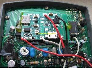
But this repair shows how I successfully managed to upgrade my old DMM to a perfectly working 400mAh 3.7V Lipo charged DMM! I first examined the circuit in my by a MAX138 controlled multimeter. The datasheet showed that this controller works on any voltage between 2.5V to 7V DC.

Li-ion Charger board with adjustable output. Above the now removed Supercap.
I already had bought above shown special li-ion charger board that also outputs an adjustable voltage upto about 9V and fits perfectly in most multimeter housings. It needs an input voltage of max 8V DC. I ordered a couple of these boards from these 2 sellers : https://nl.aliexpress.com/item/33014407148.html?spm=a2g0o.order_list.order_list_main.461.47d879d29Ntr41&gatewayAdapt=glo2nld
These links are interesting because they share more info about these boards.
Sadly a normal 18650 li-ion battery did not fit in the a bit too small VC200 housing why I used a flat 400mAH 3.7V Lipo pack instead. The size 80 x 20 x 35 battery with number 802035 was glued with some yellow hotmelt onto the board. The same I did with the charger controller board by gluing it on top of the MAX 138 controller as shown in the photo below on the right.

Next snapshot was taken to make sure I would place the function selector copper contact springs back in the right positions. The cyan button on the right pushes the on switch.

The original VC200 rubber protection sleeve (on right photo) after all those years started to become rather sticky and it was cleaned with a bit of Ammonia on a cloth. And looked as new afterwards.
The most important thing I wanted was to keep the charging selection unchanged and working! Without the need of using any other external charging cable! Not even using the USB input connector on the charger board! Else I would have decided against modifying my VC200 DMM. I found out that after removing the supercap from the board that its + track on top of this board was separated from its track on the bottom. And all GND tracks were connected with each other and to pin 39 of the MAX 138 controller which made modification very easy! VCC Pin 1 of the MAX 138 controller was now only connected to the left pin of the pushbutton switch board. And the right pin of that switchboard previously was connected to the + of the removed supercap but now no longer attached.
Which made it ideal for connecting to the output of our li-ion charger board. And the + track on the board top side of our previously connected supercap was still connected to the solar panel and the AC selector charging voltages. And now still safely can be used and connected to the + and – li-ion charger board inputs. Both AC charger voltages on the function selector (with the probes 230VAC or 9-12V AC /DC charging) are stabilised by a 3pin 78L06 regulator and with several diodes. This way a perfect input voltage is delivered to the here used Li-po battery.

The charger board +Vout was first set to about 6.1V with the tiny potentiometer which was the lowest voltage this board could deliver. Which resembles the previous voltage on which the VC200 likely was calibrated with the at the time still perfectly working supercap. Input IN- is connected to GND of pin 39 of MAX138. Input IN+ is connected to the top + track of our now removed supercap. And the Lipo of course to both BAT connections.
Here a small drawing to explain the complete modification done on this Green VC200 DMM in more detail. The Green tracks are the added changes.


Previous photo on the left showed my ready working VC200 being charged through the AC230 set charging function. The photo on the right showed measuring our present AC main voltage. Following photo shows the active Lipo charging visible by the smd red lit led. The green led above it lits when the 400mAh Lipo is fully charged.


Above photos showed the power on/off switch board and all connections, plus the 78L06 regulator circuit is clearly shown. Next last photo shows the other sideview with all made wire connections.
For the beeping sound a standard smd cmos 4011 is used in this DMM.
After this upgrade my VC200 DMM is back in action, and still Green because of the solar panel and the unchanged original charger functions!
Although Conrad sells a lot of products they also should provide decent documentation with complete schematics especially with their more expensive measuring equipment. Because they clearly are desperately missed when their products fail even after hardly been used! Previous products had wrong polarized inserted ecaps that started spraying in a solar charger board. And if you look at the photos of my VC200 DMM you’ll notice placed e-caps without decent outside plastic labels, and it is not normal that 2 new supercaps in a Green DMM already fail right after the DMM was bought brand new! Anyway it is good to know that this almost 30 year old DMM is completely
restored and like new again. After this upgrade the lifespan of this DMM probably mainly depends on the quality of the Lipo that was used here. As Lipo’s are well known for bulging.

This VC200 DMM uses a small 9V transformer to charge the Lipo battery that previous charged the removed Supercap when the 230V AC charge function is selected. Right above this small transformer the LiPo battery was glued onto the mainboard. This blue-ish transformer is partly visible situated below the LiPo on the photo that showed this Li-ion battery.
Here also a link to a very short videoclip that shows my again perfectly like new beeping ready working VC200 Green DMM.
Although my Voltcraft Green VC200 DMM now works splendidly again here last but not least a very important message! A safety warning and additional information about the measured voltages! The MAX138 controller never may be fed with voltages higher than to about 5.5 to 6V DC max! Else the controller chip heats up very fast why in the original circuit of the VC200 D7 limitted the 6V that comes out the 78L06 to about 5.28V DC. Which also protected the previous connected Supercap from exploding! Below components are measured and the circuit with all voltages drawn in following schematic.

So to prevent anything from overheating or blowing up, first make sure to set the output voltage of your Li-ion charger board to its lowest output voltage! Else your controller will act as a heater element and your precious DMM goes to kingdom come very soon! And it even may destroy the SOT-23-6 SX1308 step-up converter chip with smd code B628 in the process too! Sadly here the way the VC200 is designed also limits the current that goes into the In+ and In- inputs of the Li-ion step-up charger board to about 23,62mA. Which is calculated out 1.11V/47 Ohm. And with this resistor shorted the current rises to about 34.7mA. The converter charger board probably needs enough current and at least about 4,5V DC input.
This may still be not much to charge my Lipo but my DMM is back in action instead of being completely useless all the time!
Sadly no 18650 3.7V Li-ion battery fitted inside the VC200 case, and neither a 9V block battery. So this flat LiPo pack with charger board is for me the best option and fixes the never working Supercap powering method. And it still is possible to charge my Lipo by using the USB port on the charger board if the time comes when my Lipo is completely drained!

Here a last photo with the entire view on my now to Lipo working upgraded Voltcraft Green VC200 DMM.


Albert van Bemmelen, Weert, The Netherlands.
Please give a support by clicking on the social buttons below. Your feedback on the post is welcome. Please leave it in the comments.
P.S- If you enjoyed reading this, click here to subscribe to my blog (free subscription). That way, you’ll never miss a post. You can also forward this website link to your friends and colleagues-thanks!
Note: You can read his previous article on Fixing Internally Defect HDMi Chassis Connector On Philips 27 Inch Monitor
 (41)Dislikes
 (0)
(0)
16 Comments
Leave a Reply


Parasuraman S
October 21, 2023 at 9:31 am
Unthinkable of the height to which you might go to fix a device! What a talented professional fix! Think of starting to manufacture such new devices devoid of the handicaps as you have the skill, knowledge and expertise! Many thanks for sharing! Great work! Your efforts have overshadowed many others and you remain unmatched in this type of intricate fixes!
Albert van Bemmelen
October 21, 2023 at 5:52 pm
Although we probably could design a complete new DMM it probably would not make much sense and wouldn't be cheap either I guess. Also because the present DMM designs of today I've seen already integrate thermal cameras and other new functions that are hard to improve. In this case I was happy to fix my VC200 meter that no longer could be used otherwise.
Afterwards I also measured the current if both diode D7 and resistor R44_47 ohm are bridged over and that also increased the current that flowed into the IN+ and - inputs of the charger board to about 43 mA. And we probably here also could remove or bridge over the 78L06 regulator to gain more charging current. But that would be risky because of the present diodes D10 to D17 that likely are just small 1N4148 diodes, and because of the max current of the 78L06 that may not exceed about 100mA altogether! And not in the least because of the very small 9V transformer that is limited to only about 0.36VA of power!
Parasuraman S
October 21, 2023 at 11:17 pm
Again, head reeling explanations! Many thanks!
NATARAJAN
October 21, 2023 at 11:36 am
Sir very nice article step by step . May be you are an designer. Thanks a lot.
Albert van Bemmelen
October 24, 2023 at 12:32 am
Although I have designed a thing or two, like this one that you still can find on Jestine's Blog: => [https://jestineyong.com/diy-fully-automated-light-controlled-fan-regulator/] that still works perfectly upto this day at my brothers house!, it just takes up too much time in designing, building, and testing such a prototype.
Fixing or upgrading defect consumer electronics goes a lot quicker.
John Kent
October 21, 2023 at 3:24 pm
Not only repairing the meter but also giving one ideas on how to fix other items. Well presented solution with bags of info.
Imoudu.O
October 23, 2023 at 4:10 am
Hellow friend, infact i anticipated it must be you that would write such acticle at start of reading this acticle.I have been thinking of upgrade my dmm, but i always push the thought aside, now you have encourage me having read your arcticle.Thanks sir for sharing.
Albert van Bemmelen
October 24, 2023 at 12:56 am
I always do try to write as clear as possible accompanied by a lot of photos John. And this consequently makes my articles often a bit longer than most on this blog. Which I hope doesn't startle or annoy the (very) short article writers that often take fewer photos for their presentation.
Albert van Bemmelen
October 24, 2023 at 12:17 am
I'm sure upgrading your DMM with this charger module will be no problem Imoudu! Especially when a 18650 li-ion battery fits in your meter! Else just use a smaller size Lipo like I did!
Best of luck!
Waleed Rishmawi
October 24, 2023 at 1:36 pm
man, that is alot of details and a lot of information about the repair. thanks for sharing. I always thought of German made usually last long but I guess everything fails at some point. a very good modification congrats on the success. have a blessed day.
Albert van Bemmelen
October 24, 2023 at 9:44 pm
Yes indeed, my now about 33 year old 700 Watt Samsung Classic Microwave oven also was bought from the Conrad store and needed a repair begin this year. But the oven obviously wasn't made by Conrad. That repair was published March this year in this article: https://jestineyong.com/repair-of-31-year-old-samsung-microwave-oven/
and still works fine up to this day! Although they often used to speak about German thoroughness and reliability (in German: Deutsche Gründlichkeit und Zuverlässigkeit) everything is now probably made in foreign countries like China these days?
The best Conrad product I ever bought must be my Charge Manager 2015 (German: Akku Manager 2015) that works great mainly with charging and testing 9V Nicad/NiMH blok batteries. But is a bit dated since it doesn't do any lithium batteries.
Yogesh Panchal
October 25, 2023 at 4:14 pm
Good Job! Albert
Albert van Bemmelen
October 26, 2023 at 2:23 am
Very recently I now for the first time also used UV epoxy coating to fix my broken off HDMi port om my almost ready 27 inch Philips monitor. I hardly needed any of the 10cc UV tube substance by just scraping a few miniscule drops from the cap with my mini screwdriver.
You already used it in this older repair: https://jestineyong.com/made-uv-lamp-for-curing-uv-solder-mask/
After using it I now think this uv epoxy coating is just fantastic! Thanks for sharing! Although my UV light looks a little different with a special UV chip and closed in by a special transparant glass cased housing. (no visible UV leds like yours).
Yogesh Panchal
October 30, 2023 at 12:04 am
Very useful on Laptop/Mobile, where very delicate traces are Used.
Albert van Bemmelen
April 3, 2024 at 9:56 pm
Important Update! : to safely limit the 1A charging current that is standard set by the TP4056 chip on our charger converter board (with a 1200 ohm Prog resistor on pin 2 to ground) which is way too high for our small 400mAh li-po 3.7V battery, we increase that Prog resistor.
According to this formula: I bat charge current = (1V/R Prog) x 1200 the charge current is 1A. When we change the Prog Resistor to 10kohm we get a safe charge current of about 0.12A (See also datasheet of TP4056 charger IC).
TW
February 5, 2025 at 3:41 am
Great article Albert!
I've a solar powered Green Multimeter VC 300 with the same issue; Display fades within a few seconds. I suppose the 2 capacitors inside have died. Is there a simple solution for a external rechargeable battery pack, after removal of the two capacitors?