
High Voltage Or Lightning Caused PWM IC Burst In PRESTIGE Induction Cooker
MAKE AND MODEL NO: Prestige Induction Cooker Model No. PIC 1.0V
COMPLAINT REPORTED: Dead

PRELIMINARY OBSERVATION AND WORK:
Opened the Induction Cooker (hereinafter called ‘IC’ in this article), found a lot of cockroach eggs, excretions and a couple of living ones too! It was serving as a haven for these disgusting insects! I saw also cobwebs inside! I dismantled the boards and coil. After giving a thorough clean of inside, during which I got the top portion of the PWM IC Viper 12A, which had burst, I cleaned the PCBs too very well. I did all that outside my house, as I did not want any of these pests to start its haven here. (There is not even a single cockroach in my house, and we two ensure that none gets in! During the summer days, I have seen these trying to enter flying or running on the floor! But none survived to start migration! We use anti-cockroach sprays like ‘HIT’ periodically!)
TROUBLESHOOTING AND RECTIFICATION DONE:
After bringing the boards to my workshop table, I used the ring tester to check everything else is ok in the SMPS section. As all the LEDS lit brightly indicating that there are no shorts in the primary or secondary, I replaced the burst IC. Looked for any defective components in the primary or secondary section. Found the 10 Ohm Fusable Resistor open in the AC input section. But Fuse was intact. Replaced the Resistor. As I saw the small induction coil (through which the DC comes to IGBT section) had collected fungus and looked to be in a bad condition, replaced it. It was a good thing I did, as one leg of it came off itself! Normally, technicians do not check this, even though this plays an important role! Applied power and noticed that the Panel got on and it responded to commands. So, after doing a thorough dry solder patch-up, and replacing all the electrolytic capacitors and the front panel switches (a few of which were showing high resistance), I rechecked the high watt resistors, diodes and transistors on the board. All looked to be good. So, placed the board back in its case, placed the coil on top of it, took the panel to the side for operating it, kept the ceramic top on the coil, kept water in a stainless steel vessel and applied power. All looked well for a few minutes. But suddenly the IC broke down tripping the MCB of that line in my house. I knew that IGBT had failed, which meant that more preventive work had to be carried out. Once again dismantled the IC. Removed the failed IGBT, H15R1203. As a routine and regular method of rectification in almost all ICs, replaced all the high watt resistors, IGBT base driving transistors SS8050 and SS8550.
Since exact values of resistors were not available, I had to connect a few in series to get the correct value. For example, for 240K, I used two 120K in series; for 200K, two 100K in series etc. As I wanted to know the root cause of the failure, I checked the transistors using Analogue Multimeter, keeping it in X1 Ohm range, as advised by Jestine Yong in his repair books. As the readings between Base-Emitter and Base-Collector were not even, I knew that the transistor had developed leak. I compared it with the new ones to make sure and it showed correct readings on both sides. So, that was the culprit. Then once again checked the other components on the board for any leak and conformation to the values marked, for which sometimes I had to lift one leg (not mine, the component’s (LOL)). As I could not find anything wrong, I replaced the IGBT with FGA25N120, which is a better and sturdy one from experience, reassembled and tried heating like before. This time it worked very well. After trying it a few times, fixed the screws of the bottom cover and left it in my kitchen for couple of days. As it was found to be working without any problems, informed the customer to come and collect. Mission accomplished generating another ‘satisfaction’ ball, which was happy to roll itself into its collection bag!
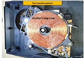
TIME FOR PICTURES TO REVEAL THE WORK DONE:
This article was prepared for you by Parasuraman Subramanian from India. He is 70 years old and has more than 30 years’ experience in handling antique equipment like Valve Radio, Amps, Reel Tape Recorders and currently studying latest tech-classes conducted by Kerala State Electronics Technicians’ Association. He has done graduation in BBA degree, private diploma in Radio Engineering and retired as MD of a USA company. Presently working as Consultant to Hospital and other institutions.
Please give a support by clicking on the social buttons below. Your feedback on the post is welcome. Please leave it in the comments.
P.S-If you enjoyed reading this, click here to subscribe to my blog (free subscription). That way, you’ll never miss a post. You can also forward this website link to your friends and colleagues-thanks!
You may check on his previous repair article below:
https://jestineyong.com/lightning-struck-akai-active-surround-system-restored/
 (54)Dislikes
 (0)
(0)
20 Comments
Leave a Reply


Albert van Bemmelen
September 22, 2020 at 6:39 pm
You may as well also add 'Professional Induction Cooker Repair Engineer' to your title, because there is nothing that escapes your experienced attention in order to get those fixed either!
Parasuraman S
September 23, 2020 at 10:58 am
Many thanks; that's a lot of pat on my back! Enjoyed!
Paris Azis
September 22, 2020 at 9:12 pm
Good job, Parasuraman. Thank you for sharing it!
Are you sure about the suggestion of measuring semiconductor junctions using the Rx1Ω on your analog multimeter?
I believe that something is wrong here. Most analog multimeters put out 150mA in this range, which is catastrophic for small signal transistors.
On the other side, Fluke (as a reliable reference) uses 1mA for this test. In accordance to this reference, the best range when working with analog instrument is the Rx1KΩ.
Range Rx1Ω, can very easily destroy the base junction of any small signal transistor under such tests.
I noticed this statement of yours once again, in another article you published, and thought that it was a misprinted number. Now it’s the second time, meaning that somewhere is the mistake hidden. Please confirm this with Jestine as well.
One of my first lessons in electronics was exactly this one: “never use the Rx1Ω range when testing transistor junctions or sensitive diodes”. Another good example is the 1N4148 diode. Its maximum forward current is only 7A. No way to use 150mA for testing it. It’s prohibitive.
Paris Azis
September 22, 2020 at 9:17 pm
...75mA for the 1N4148...not 7A!
The demon of automatic correction...!!
Henrique J. G. Ulbrich
September 22, 2020 at 11:05 pm
I agree with You, Paris. This was one of the first things I learned in the old 1960 Years, when migrating slowly from tubes to transistors. I never tested transistors and diodes in the Rx1 Ohms scale. Up to now, I never destroyed any transistor or diode. And my tests were always successful. This statement needs further explanation.
Paris Azis
September 23, 2020 at 2:13 pm
Hey Henrique
This restriction is 100% valid. (I belong to the “old school”, as you do). We both have been grown up with these instruments at hand and it is quite natural for us to remember similar instructions from our teachers...
A second thing I cannot forget, is the need of a VTVM in order to measure the AGC voltage on a vacuum tube receiver, along with all its theoretical explanation (which is, by the way, the very high resistance of the resistor across which the AGC voltage was developed. An ordinary 20KΩ/V sensitive multimeter of that time would give completely erroneous AGC voltage indication, i.e. much less than the real magnitude). Therefore the input resistance of the instrument had to be much much higher than the impedance of the AGC circuit, in order to prevent any loading of the circuit and producing thereby accurate and reliable measurements.
Needless to say that I bought my VTVM very soon after this instruction, which is fully operational up today! And I still use it especially when I want to measure (safely for the instrument itself) high voltages, up to 1500V/DC/AC with its standard probe, or up to 30.000V/DC/AC with its accessory high voltage probe.
This instrument was really indispensable in its time. The measurement of the high voltage feeding the anode of the CRT was a very simple task to perform...
Good old days...
Best Regards!
Parasuraman S
September 23, 2020 at 11:01 am
I use Jestine Yong's directions in testing semiconductor testing. He always advised to test it in x1 range and repeat the test in x10 range also, as both ranges use different voltages. I have found these to be very, very useful and more accurate than even the Peak Atlas. I have mentioned this in one of my previous articles!
Many thanks for your detailed comments and observation!
Paris Azis
September 24, 2020 at 5:53 pm
Hi Parasuraman
No matter the exclamation mark you put in your closing phrase, I can easily see hostility in your answer, which led me to answer you again, just in order to clarify at least how I am thinking, given our cultural differences which are unavoidably always present.
In any case, my purpose is not to insult others through commenting. On the contrary, I always seek the truth and when I find it I defend it later on.
I read your text again and again as regards the part of transistor testing. Your argument was that you replaced these transistors because of “uneven” indications. And then you explained the failure upon this base.
Unfortunately, there was never “even” indication and there will never be, as regards BJT transistor junctions B-E and B-C. Their Vforward will ALWAYS differ.
This is due to the fact that the emitter of the transistor is more heavily doped with silicon. This in turn makes the Vf voltage of the B-E junction a little bigger than the one of the B-C.
The difference is hardly seen with an analog meter, but it’s always there. Measured with a digital multimeter, it’s just a few millivolts above the B-C junction.
I magnified the relevant photos you published. This fact is present on both pairs of them. The second one is simply more obvious.
There are only a few exceptions to this rule (the assymetrical junction voltages I mean). I just remember the germanium type AC130, used in transistorized B/W TV circuits, in the synchronization separator stage. It was characterized as a symmetrical transistor directly on the schematic notifications, along with the instruction “the stage won’t work with any other replacement”.(SABA sets)...
Next, you say in your text, that this assymetry justifies leakage of the transistor. But this is not true.
Leakages are revealed when the polarity of the test voltage is reversed. Not when measuring Vf, which detects only shorts and opens.
You answered me that you follow Jestine Yong’s instructions...
I support the idea that a pupil should follow his teacher’s instructions, but teachers are not mistake-less. They are humans, not supermen.
In this case, about the range of testing small signal transistors:
How can one believe that a transistor of this family which normally has its base working in the μA range (an ordinarily high “beta” type), would happily accept 150mA in its base? Well, my teacher obviously didn’t!
I would agree in using this range only with power transistors, like the good old 2N3055, but never with a 2N3904...
Apart from all of these above, my idea about commenting an article, is, of course to recognize the effort the author put on it, this is obvious, but there is also another aspect always present.
A published article, teaches people. Especially newcomers in the field. These people need solid base in order to learn things about electronics.
Eventually the author is willy-nilly exposed to a large number of readers. They will react according to their accumulated knowledge. You need to accept that!
And the question is, how do you expect them to react when they see wrong ideas spreading all over the community these articles are targeted to?
And let me closing with a motto:” The person that always tells you that you are good and mistake-less, is not worth your trust, nor being considered as a friend of yours”.
Hopefully I made myself clear, which was my exclusive intention...
Parasuraman S
September 27, 2020 at 10:21 pm
Yes, very clear and vivid. Many thanks. You are further right that we need people who criticize than appreciate, as the former will always teach us something and help us think differently from our usual path. Your contribution, therefore, is welcome and special thanks for it. There was no sarcastic intention as assumed by you in that exclamation mark. It was an exclamation of appreciation. I fully agree with your technical arguments. But what I have practiced and experienced has taught me this, though technically unacceptable. Kindly therefore bear with me! My apologies if I have hurt you in any way. I never want to hurt anyone and will not even think of it directly or indirectly. (By the way, I never realized until now that an exclamation mark can lead one to misunderstand) I look forward to your expert comments and guidance in future also.
Paris Azis
September 28, 2020 at 6:34 pm
Dear, dear Parasuraman...
You always had and you still have my full respect. No question about that.
At last I read from you words of wisdom not seen in the first place, as I expected, but nevertheless they are here no matter the delay. Your explanation about your experience and practicing being technically unacceptable simply confirms what I had suspected. Therefore is fully acceptable. It happened to me as well. You are not the only one being led in wrong technical conclusion(s) standing on a wrong base. There are many people and there will always be many others falling in such pitfalls, but this is quite natural. Knowledge is obtained through difficult ways and paths.
The point is if our "ego" is so strong that rejects unexpected "incoming signals", or flexible enough in order to realize that "it is a good chance to learn something new here"...
In any case I can assure you about a few things.
First, that I am not hurt by you in any way and therefore your apologies have no reason to exist.
I would rather reverse your phrase, putting myself in your shoes. The apologies in this respect are mine.
Next to that, be sure that you will receive again similar comments from me, under the same light of view, every time I will see statements that violate the established theory.
At this point, I must make clear once again that I am not talking about "my" arguments with the possessive meaning of the word, but with the meaning of the established theory on which my argument stands.
This simply means that I have always available the theoretical proof about my own technical statements when commenting, while I remain silent when it comes in things I don't know, but which trigger me to search about their truth for their further acceptance of them of myself.
In any case, my purpose was always to bring in surface what is scientifically correct, rejecting what it is not.
I can also assure you that I can read the feelings of a person's writings when it comes to interpersonal relations...
After reading very carefully every single word of your last comment, I would like to reassure you that I have never had hard feelings against you, neither against anyone else (especially of the article authors of this blog, being myself one of them).
Therefore,...case closed.
My best regards!
Parasuraman S
September 29, 2020 at 7:26 pm
Yes, case is closed, like a Perry Mason case. (LOL)
Parasuraman S
September 24, 2020 at 2:53 pm
I too have never damaged any semiconductors by measuring in X1 range, including IN4148. So, experiences surprise me! May be Jestine Yong can clarify.
Humberto
September 23, 2020 at 6:41 am
Hi Parasuraman, a complex fix, but at the end you have brought another device to the life. Congratulations. By the way I´ve never fixed this kind of device, but I would like.
Parasuraman S
September 23, 2020 at 11:02 am
Shall I courier one defective piece! (LOL) Many thanks, Huberto! You are always very prompt in encouraging!
Waleed Rishmawi
September 24, 2020 at 4:49 pm
hey man. thanks again for your repair and the details. keep up the good work my friend.
Parasuraman S
September 24, 2020 at 11:50 pm
Many thanks, my friend!
Yogesh Panchal
September 24, 2020 at 7:26 pm
Sir, you have made this equipment more younger buy installing new teeth.
Thanks! for Sharing.
Parasuraman S
September 24, 2020 at 11:50 pm
Many thanks!
Paul
September 26, 2020 at 12:44 pm
"different voltages" > "DIFFERENT CURRENTS" !!!
Paris Azis
September 26, 2020 at 4:36 pm
You are right Paul.
Analog instruments, when measuring resistance and when changing ranges, put out different currents. Not different voltages. These ranges behave like constant current sources rather than voltage sources. Their voltage output simply depends upon the number of batteries included in the instrument, for the relevant measurements (I.e. 1,5V if there I’m only one alkaline battery included in it, or 3 V, if there are two of them connected in series). There are some cases where for the Rx10KΩ range exclusively, a 9Volt battery is also included. My first instrument was using a 22V battery for this range, not being available nowadays.
On the other hand, this fact about the number of batteries and their nominal voltages, explains clearly their function, based on Ohm’s Law, in combination with Kirchhoff’s current Laws...