
How To Test PWM Gate Drive Signal Pulse Using Single Bright LED
It is difficult to check PWM IC working in SMPS without Oscilloscope. Came across trick for testing which give us indication if PWM generating Gate drive signal pulse or not.
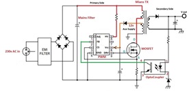
Reference Circuit for SMPS Switching:

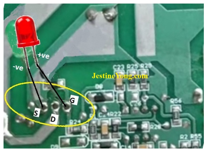
First of all, remove the mosfet from the Circuit under test & connect the LED as per the following diagram. Connect LED’s Anode (+ve) to Gate pad & Cathode (-ve) to either Source of Mosfet pad or –ve pin of
mains capacitor on primary side.


For safer side connect the SMPS circuit on the “SERIES BULB TEST BOARD”.
Now turn ON the SMPS if LED starts blinking/flashing indicates PWM IC is working & generating Gate drive pulse.

This article was prepared for you by Yogesh Panchal who works as a Computer Hardware Engineer in Mumbai India.
P.S- Do you know of any your friends who would benefit from this content that you are reading now? If so, forward this website to your friends or you can invite your friends to subscribe to my newsletter for free in this Link.
Note: You can check his previous repair articles on Philips MMS 430 Volume Control Unit Modification Wiring Details
 (53)Dislikes
 (0)
(0)
29 Comments
Leave a Reply


Albert van Bemmelen
March 22, 2025 at 2:49 pm
WOW Yogesh! That is a very innovative trick you used to check if a PWM circuit is working!
That only leaves checking the mosfet if the power circuit previously failed to work!
Yogesh Panchal
March 22, 2025 at 3:57 pm
Thanks!Albert
Ranjit Fernando
March 23, 2025 at 11:23 pm
Thank you so much for sharing this.
Ranjit/Srilanka
Mike Scott Hansen
April 21, 2025 at 6:02 am
Thanks so much Albert!
Tyrone Arendse
March 22, 2025 at 2:59 pm
Hi, thank you for sharing this information
Yogesh Panchal
March 22, 2025 at 3:58 pm
Your Welcome!Tyrone Arendse
Paul
March 22, 2025 at 3:03 pm
Very useful trick, thanks Yogesh. I guess if the LED does flash you would check the MOSFET, or where else do you suspect there maybe an issue?
Yogesh Panchal
March 22, 2025 at 4:08 pm
Thank you!Paul
The suspect components are the main transformer,snubber circuit components connected to the primary winding also check Components connected to the MOSFET, Still problem then replace and check the PWM IC as it may misbehave on load if bad also check for dry solder.
tree
March 22, 2025 at 3:07 pm
Great article. Thanks God bless you.
Waleed Rishmawi
March 22, 2025 at 3:24 pm
thanks for sharing that trick I appreciate it very much. have a blessed day
Yogesh Panchal
March 22, 2025 at 8:22 pm
Thanks!Waleed
MUYKIT
March 22, 2025 at 4:05 pm
Engineer Yogesh, a good pictoral illustration and even more clear drawings to effectively drive a point home, infact a video is quite needless. Its completely understood to me. Very useful information. You see, Yogesh there is no cheap oscilloscope obtainable.
Yogesh Panchal
March 22, 2025 at 8:25 pm
Thank you! MUYKIT
Yogesh Panchal
March 22, 2025 at 4:09 pm
You are Welcome!tree
Parasuraman S
March 22, 2025 at 4:29 pm
Many thanks for sharing this useful tip, though I do check the gate drive pulse similarly and may times use Analogue multimeter in AC mode. The explanation and diagrams are really superb! You have progressed well in your article writing in leaps and bounds! All the very best!
Yogesh Panchal
March 22, 2025 at 8:28 pm
Thank You! sir
Articles Finally Polished by Jestine Sir.
Mark J
March 23, 2025 at 2:49 am
Yogesh great article. Very informative. Thank you for sharing.
Yogesh Panchal
March 23, 2025 at 3:23 pm
Thank you! Mark J
Bruno Nai
March 23, 2025 at 8:25 pm
Thank you.. I appreciate
Yogesh Panchal
March 23, 2025 at 11:02 pm
You're welcome!Bruno Nai
Yogesh Panchal
March 24, 2025 at 1:48 pm
You're Welcome! Bruno Nai
Bruno Nai
March 23, 2025 at 8:35 pm
Thanks again ... Does this excellent trick work with STR and the likes please..
Once again I admire the logic involved in coming up with this great trick
Yogesh Panchal
March 23, 2025 at 11:08 pm
Bruno Nai
Yes,we can test STR Power supply too.
Yogesh Panchal
March 24, 2025 at 1:51 pm
Bruno Nai,
Yes, It works with STR Power supply too.
Mark
March 24, 2025 at 7:32 pm
Thanks for sharing that little trick Yogesh.
Yogesh Panchal
March 25, 2025 at 10:50 pm
you're Welcome!Mark
tree
March 26, 2025 at 2:56 pm
"SERIES BULB TEST BOARD" means connecting a bulb instead of a fuse, right? Thank you.
Yogesh Panchal
March 27, 2025 at 3:37 pm
Tree,
Yes....
Ulises Aguilar
July 27, 2025 at 6:42 am
nice tip Sir