
Level Shifter ICs Found Defective In Videocon LED TV MODEL LEDVJW32HH-2FA A1

This TV was brought to me by a friend of my regular customer with the complaint that there was vertical shifting of picture, splitting, and jumping.
I opened the set and did a thorough cleaning of inside.
Then checked the voltages on the panel and found the following:
The voltages were quite normal. After consulting my techie friends, who were of opinion that some tracks would have to be cut from the level shifter IC, I kept the TV aside for attending to it later. Anyhow, as I was not getting time and already taking my pending load to one of my Techie Friends, I allowed it to get solved by him.
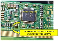
He checked the Level Shifter IC outputs and found that the VGL/VGH shifting was not taking place in one of the outputs. He suspected both ICs to be defective and ordered for replacement. I left the TV in his place and returned home to pick it up later.
As the panel was not working properly even after replacement of these two ICs, he ordered for a second hand panel, which worked well for watching, but with appearing horizontal lines, which might go unnoticed and did not hamper view. (My guess is that the tiny hair like tracks of the level shifter ICs would have got damaged due to replacement of the ICs, necessitating the need for a change of panel) These lines just appeared suddenly for a few seconds and vanished.
Then when I went there to collect the TV after a few days, I found the TV to be viewable and informed the customer along with the pictures and videos. He was satisfied and therefore I brought the TV back to my home and delivered it. Customer satisfaction indeed was responsible for adding one more to my collection bag. Here is the final picture:
This article was prepared for you by Parasuraman Subramanian from India. He is 72 years old and has more than 30 years’ experience in handling antique equipment like Valve Radio, Amps, Reel Tape Recorders and currently studying latest tech-classes conducted by Kerala State Electronics Technicians’ Association. He has done graduation in BBA degree, private diploma in Radio Engineering and retired as MD of a USA company. Presently working as Consultant to Hospital and other institutions.
Please give a support by clicking on the social buttons below. Your feedback on the post is welcome. Please leave it in the comments.
P.S-If you enjoyed reading this, click here to subscribe to my blog (free subscription). That way, you’ll never miss a post. You can also forward this website link to your friends and colleagues-thanks!
You may check on his previous repair article below:
https://jestineyong.com/original-eight-pin-volume-control-replaced-in-pioneer-amp-model-no-sa610/
 (48)Dislikes
 (0)
(0)
11 Comments
Leave a Reply


Albert van Bemmelen
April 29, 2021 at 3:03 pm
I know too little of these methods in which you just cut some coppertracks or do some other kind of mysterious 'trick' to make disappear the problem. And sadly reading this rather short repair article again doesn't make any of it any clearer. There also is so much written about fixing problems in all the collected TV repair e-books I already own that I'm afraid that closing that knowledge gap is already completely losing my interest.
Humberto
April 29, 2021 at 10:41 pm
Hi Albert, I´ve watched some videos of TV repair and they give the total solution by cutting some tracks in the T-Com Card; but I do not understand this yet.
Parasuraman S
April 30, 2021 at 9:01 pm
I had not done any cutting tracks in this case. My friend changed the panel with an old one as mentioned by me in the article, which had some minor problems only. Many thanks for your comments!
ombra32
April 29, 2021 at 7:57 pm
I'm sorry, but I don't understand.
What was the problem and how was it solved?
Regards,
Marco
Parasuraman S
April 30, 2021 at 9:03 pm
Kindly see the first picture. Since posting a video is not possible, nor is it possible to capture the fault as it is too fast, I have provided a description. The problem was shifting of pictures from bottom to half screen and horizontal lines blocking half view. Many thanks for your comments!
William Shaw
April 29, 2021 at 10:10 pm
Does your techie friend use schematics to troubleshoot? It would seem that the vast variances in models would make it very difficult to troubleshoot without it.
Thanks for the info,
William
Parasuraman S
April 30, 2021 at 9:05 pm
Most of the voltage details on scaler board, T-con board, power supply board and main boards are known to my techie friends who are experts as they handle around ten cases per day.
Many thanks for your comments!
Winston
May 1, 2021 at 5:30 am
I am also interested in solving this jitter problem. Do you need an oscilloscope to check input and output signals to these IC's? Which repair guide version details this process for me? Do I need a 200MHz scope? I don't want to buy one and find there is an easier way to solve this problem!
Yogesh Panchal
April 30, 2021 at 4:14 pm
Sir,
As you are well aware about Panel cost. it is very high compare to the New Unit be careful while removing those SMD IC which are soldered by lead free solder.use a good quality Flux(AMTECH Flux 213 or 559 Flux liquid or gel )or any other brand and temperature controlled rework hot air station.
damaging those Hair line traces are worst thing to repair without Microscope camera.
Parasuraman S
April 30, 2021 at 9:06 pm
Yes, you are right Yogesh! We use liquid flux only. Your caution is noted and we shall take care! Many thanks for your comments!
nader bahrami
May 15, 2021 at 4:27 am
hi sir
Parasuraman S
Hello dear colleague. This is a disadvantage of the panel and its side connections because the side information is inserted with the IC and sometimes interrupted, which can be replaced with a car bonding device. In some models, where there are no side ICs, you can disconnect from the lower ICs, but the high-resolution image is not very accurate.