
Restoration of a Samsung CRT TV by Rejuvenating CRT

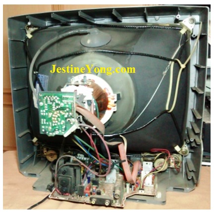
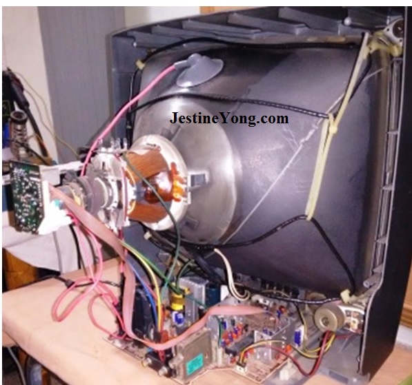
I got a Samsung CRT TV Model CB20E4V2X with the complaint that the picture diminished day by day and only sound remained, after which it became dead completely. So, I went through the routine of confirming the complaint by switching it on at my desktop, opening the cover, cleaning it up and removing the board for a visual inspection, after discharging the anode. I noticed that a few capacitors were bulgy in the secondary, 125V line, CRT PCB and around the LOT. The LOT (Line output transformer or FBT – Flyback Transformer) itself was not in a good shape, as the wire going to the anode was wrapped with tape and had collected a lot of black dust. You can see it from the first picture I took before removing the board:
Nevertheless, I cleaned the CRT as well as this LOT to the best possible limit. Replaced the capacitors. Noticed dry solder on the board as well as on the CRT PCB.

Patched up all the dry solder on the main board as well as the CRT PCB. Cleaned the board and CRT PCB thoroughly. After doing another visual examination, reconnected the board. The set came on, with completely dark screen. When I increased the screen voltage, there was mild green raster with retrace lines. Neither the menu nor any other uController based displays could be seen! When I switched off and did a discharge of the anode, there was no EHT discharge, which showed that the LOT must be weak. So, I decided to replace the LOT.
Got a replacement for as low a price of Rs.220 (about 3.25 US$). Replaced the LOT. Simultaneously followed the testing methods described in CRT Television Troubleshooting Guide by Humphrey Kimathi (Chapter 11: HV is present but the screen is dark). Heater voltage of 9V AC was ok. There were no resistors on its path. After checking the other points mentioned by him like screen voltage, RGB voltages etc, replaced the TDA6107Q IC on the CRT PCB. Then tracked the ABL circuit. Noticed that one resistor had increased its value. Replaced it. Connected the board, with the same result. So, once again discharged the Anode and found there was a crackling noise indicating that enough EHT was present now! Removed the board and connected it to another CRT that I have for testing purposes. The raster was present!
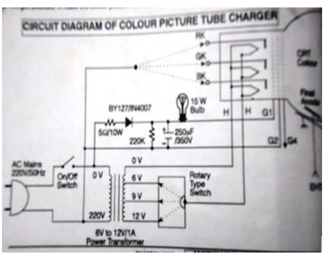
So, there was nothing wrong with the board now! I had connected a China ES board to the Samsung TV CRT and found green raster with retrace lines, confirming that the tube indeed was defective. In the Samsung circuit, there is a feedback sensor that shuts down the system, if there is an imbalance between the guns. So, it will not open out RGB. Whereas, in the China Kit, there is nothing like that! I turned my attention to the CRT and guessed that the RGB Cathodes were weak. I had come across a guidance given on the inner cover of every Modern Colour Television Circuits released by BPB Publications, New Delhi, about rejuvenating old CRT. Here are the circuits:

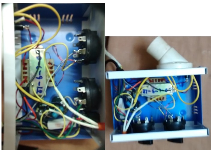
I bought one eliminator box, and other components mentioned there in and assembled the CRT rejuvenator. This took many hours, as drilling on the cabinet and fixing the knobs, transformer, bulb holder, wiring, connecting a CRT socket securing the loose wires on an insulated wire to the ground pin of the CRT socket etc. are all a laborious job! The whole thing cost me around Rs.600/- (around 8.60 US$)
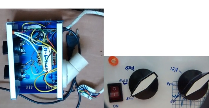
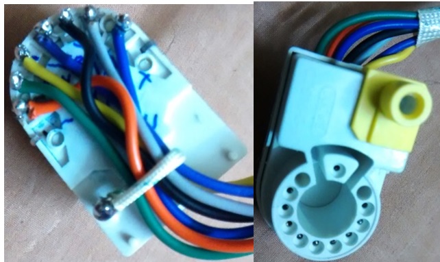
The knobs have 6V, 9V and 12V AC selector for the heaters and Blue, Green and Red selection for the RGB Cathodes. The methods to be followed are as given below:
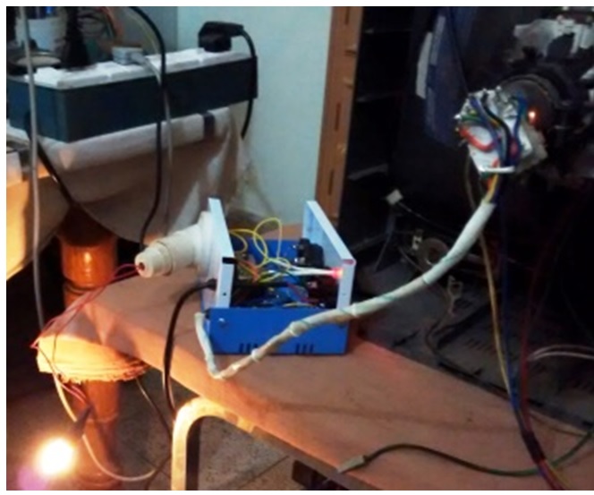
Discharge the anode and remove the board. The CRT should be bear without any connections on its neck. Insert the CRT socket. Select the desired heater voltages (in this case 9V), and select any one of the colours, and switch on. As soon as we switch on, after the filament glows, the 15W bulb will glow momentarily and might blink a few times and go off. This is the time the carbon deposits inside the CRT gets burnt or displaced. After a few minutes, the filament of the 15W will start glowing slowly and become very bright. We have to wait for about 3 to 5 minutes after its full glow. Then switch off and change the Cathode selector switch to the next colour.
Repeat the process. After completion of the charging of 3 Cathodes, once again check whether these are properly charged, i.e., whether the bulb glows to its full within a few seconds of switching on and stays steady. If not, we have to repeat the process several times, until this stage is reached. It might take several minutes and even hours. If the cathodes are not getting charged, we may have to increase the voltage of the filament to 12 and retry. If there is no glow of the bulb, it means that the CRT cannot be rejuvenated.
In my case, the Cathodes got rejuvenated very well! See the bulb glowing (I used a 15W, 230V AC thread type bulb connecting it to an adapter to fit in the bulb holder)
After finishing the recharging, and rechecking each cathode once again, disconnected the rejuvenator and connected the board back.
Caution: When the board is connected and switched on, there were rare cases of heavy internal arcing and neck cracking. So, as a precaution, it is suggested by one of the experts in the field to disconnect the supply to the yoke, keep the focus and screen control to the minimum and then switch on. After switching on, the focus and screen control should be increased slowly until we get a spot on the screen. This spot should not be allowed to be there for too long, as it will burn and leave a permanent mark on the front screen. The moment we see the spot, just switch off, remove the power plug, discharge the anode and then connect the yoke. It is learnt from experience, this process will eliminate the chances of internal arcing due to carbon deposits falling on wrong places, when the recharging of the tube takes place. In yet another place in the website, I remember to have read that we should keep the tube on its face for sometime, and tap the neck with a rubber mallet or with a screwdriver handle wrapped with a rubber ring, gently so that the carbon falls far away from the neck. I did both before switching on.
Hurray! The TV started working like a new one! The CRT guns started shooting (I have deliberately selected an appropriate picture to imply it, rather to give a James Bond Victorious effect!)

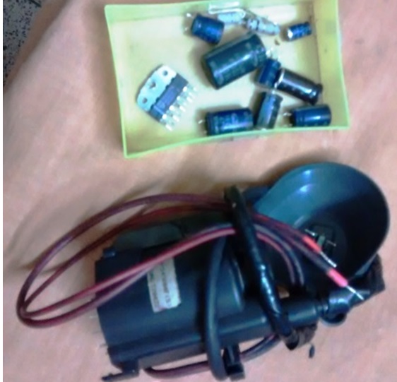
Here is the picture of the components replaced:
Another job done satisfactorily, learning many things new in the process!

This article was prepared for you by Parasuraman Subramanian from India. He is 66 years old and has more than 30 years’ experience in handling antiques equipment Valve Radio, Amps, Reel Tape Recorders and currently studying latest techs classes conduct by Kerala State Electronics Technicians’ Association. He was a BBA graduate, retired as MD of a USA company.
Please give a support by clicking on the social buttons below. Your feedback on the post is welcome. Please leave it in the comments.
P.S-If you enjoyed reading this, click here to subscribe to my blog (free subscription). That way, you’ll never miss a post. You can also forward this website link to your friends and colleagues-thanks!
You may check on his previous repair article below:
https://www.jestineyong.com/restoration-of-jvc-mx-j170v-component-system/
 (138)Dislikes
 (0)
(0)
18 Comments
Leave a Reply


Robert Calk
April 18, 2016 at 3:50 pm
Good job, Parasuraman. Thanks for the tips.
suranga bandara, Suranga Electronics
April 18, 2016 at 4:44 pm
Hi Mr- Parasuraman Subramanian,
Great work, you have shown your expertise.
Thank you so much !
Albert van Bemmelen
April 18, 2016 at 5:17 pm
I Salute you dear Parasuraman Subramanian! This article explores
something I never have done! (and also hope never have to!).
It is a very difficult process with unsure results. And I am not
sure if I could do this satisfactory myself. And in these fields
of becoming ancient technology no one better than you is
qualified ! (The TV picture you showed doesn't look very promising
though?)
Probably the only CRT tubes that I will remain using are most
likely only in my Tektronix, Philips, Kenwood and other
Oscilloscopes. (and in a few old still working TV's I saved until
someone wants them. And Thank you Parasuraman for the Schematics
you provided that however maybe could have been published in a
little better detail or quality. Since I've never seen these
interesting schematics before. (;-)
Parasuraman S
April 18, 2016 at 8:07 pm
The picture I chose was from a running video and not a still picture and that time, the video was like that.(The lady is wearing a net on her hat) The TV is working like new now, that is for sure, as I have seen the happy gleam in the eyes of the customer who took delivery!
About the schematic, it is a bigger one and cannot be scanned in my A4 scanner. So, I used an external zoom lens. But what is not perhaps clean enough is compensated by the other diagram. The circuit is very simply. Two lines of 230V primary is selected for giving high voltage to the two grids. One through a current limiting resistor, rectified by IN4007 diode and smoothed by 250mfd/350V Cap and fed to Grid1. The other line is negative of the high voltage, which is fed to Grid2(Screen) and to Cathodes of the 3 colours by selection. One 220K bleeder resistor is provided between the positive and negative. The 230V is then stepped down through a transformer which has 0-6-9-12 tapping. 0 is used as ground, and 6, 9 or 12 is selected appropriately for the filament voltage.
albert van bemmelen
April 19, 2016 at 3:09 am
Understood. Taking a photo was of course the best solution.
And now any reader is able to print it fit on A4 format after
all.
When I sometimes am copying - reverse technology wise - an
electronic device onto an exact schematic on paper, I use
the IC's from the Datasheet in smaller format. I do this
by using my Brother printer scanner and place all in the
Device used components in reduced format on a sheet of
paper. This way I am able to fit the complete circuit on
one (or 2 if too many components are used) A4 sheet(s) of
paper before I continue by drawing all connections.
By 'beep' testing all connections with a Digital Meter.
But I first always take (Macro) snapshots of the Device
and all of its components.
And thank you for your detailed reply of your Tube rejuvenator!
beh
April 18, 2016 at 9:11 pm
Hi PARASURMAN
Thanks and congratulation for this great repair this CRT charger is highly required also for me .please tell me how much more than 8.50 USD i have to send you to post me one these charger.
thanks & regards
beh
Parasuraman S
April 18, 2016 at 9:43 pm
It is assembled by me looking at the circuit diagram given. You can also do so at your end, as these are available parts (One 230V to 12V step down transformer with tapping of 0-6-9-12, one IN4007, one 5 Ohms 5W resistor, one 220K 2W resistor, one 250Mfd/350V capacitor, on/off switch with builtin neon, one led indicator with a 1.2K resistor from 6V AC line,two single pole three way rotary switches rated for 3A 230V, one box that can house all these, one 230V AC bulb holder, one 15W Bulb). Cost for sending one charger from India to your place would be prohibitively high! Moreover I do not have any facility to do so, as it involves a lot of custom formalities and other time consuming and packing work. Perhaps Jestine Yong might help you!
beh
April 19, 2016 at 11:05 am
Hi Parasuranam
yes this is the true and the best thing to do is to assemble this cir cute by my own .all these part s are available here.
thanks
beh
Paris Azis
April 19, 2016 at 2:57 am
Good job, Parasuraman. Thank you for sharing it. The drawings of the tester/rejuvenator, although CRT TV has almost disappeared from the scene, are interesting as well.
Greetings
Gopal Sharma
April 19, 2016 at 2:18 pm
Good job sir, but as per my experience , charged CRT's does not last longer. It might run for 1 or 2 months then it becomes unusable and no charging works after that. what is your opinion?
Parasuraman S
April 19, 2016 at 11:37 pm
According to my friends who are experts in this field, the tube might run for a couple of years or more. One important point to be remembered is that the recharged TV should never be left idle for a long time. It has to be in use, if possible daily. When replacement CRT is no longer available, the only option we have, is this method of rejuvenating. It is better to take this risk than abandoning the TV!
Yogesh Panchal
April 19, 2016 at 10:36 pm
Sir,
Thanks for the rejuvenation tips, I have never heard before.
Humberto
April 19, 2016 at 11:27 pm
Hi Parasuraman, you have done another professional repair, as usual. Congrats.
Geoffrey
April 20, 2016 at 10:58 am
Thanks for your rejuvenating CRT circuit. Your great.
Graham
April 22, 2016 at 2:45 pm
Hello Parasuraman this article takes me back a long time & i can't remember when i last worked on a CRT TV. I started work as an apprentice electronics tech at a factory when they first started making Colour TV's in England, so that shows how old i am now 🙂
Now i work on low voltage car modules (i have had enough of high voltage shocks) but i enjoy articles like your's especially when you fabricate your own equipment. Very nice article Parasuraman & greetings from England.
Graham
Parasuraman S
April 22, 2016 at 11:12 pm
I thank one and all for your warm appreciation, encouragement and support, which is always the fuel in propelling ahead!
Dinesh Shinde
January 17, 2018 at 11:24 am
Thanks sir, this problem is those tv witch croma ic use TDA 8841/42/43/44.This ic use in some BPL and samsung tv,s.In those tv set canect any other kit working fine. Thanks.
David Pilgrim
May 18, 2022 at 10:06 pm
Great efforts
Lack of this knowledge has mad so many screens cast away prematurely. i will do my best to obtain knowledge of this rejuvenator design to save issues in my area.