
Scaler Board Replacement In Samsung LED TV Model UA32EH4800R
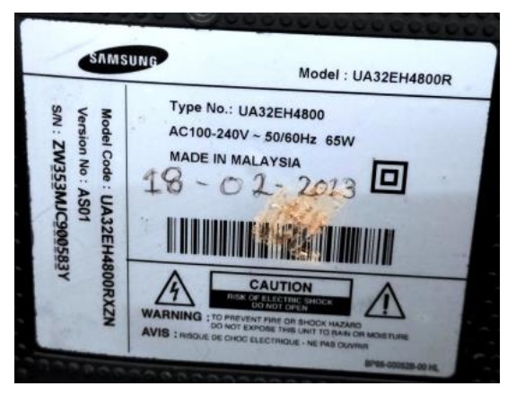
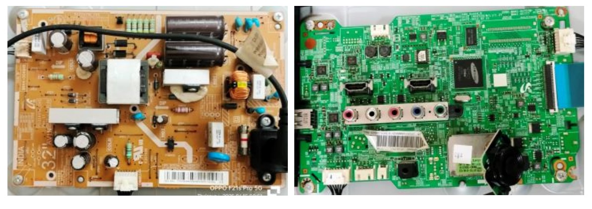
This TV belonged to one of our close family friends and was first brought in January, 2025 due to a power failure. From the label, you could perhaps see that the TV was 12 years old! I had replaced the board as the PWM was not available in the market and the PS board was with PFC circuit. I have submitted a report of this to this forum in yet another article, which is in queue. This time (June, 2025), the complaint was ‘no display, but sound ok!’ When I gently tapped on the screen, the backlight could be seen indicating that the problem was not due to it. I am sharing a couple of snaps of the PS Board and Mother Board below for the sake of refreshment of memory:
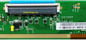
The first step was to check the voltage that goes to the scalar board. The panel in this TV worked with a 12V supply, I checked the voltage at the input point and noticed that it was ok. Following picture is that of the input point:
The voltage at the point marked above, before the F101 fuse was ok. But the voltage at the other end dropping and oscillating between 3 to 5V, indicating that there was something loading. When I checked the resistance of this fuse after disconnecting power, which should show zero, was reading around 230 Ohms. This is a peculiar type of fuse that would increase its resistance on a shorted load. The marking on this green SMD fuse was ‘K’. Though I searched for a datasheet of this fuse, I could not fetch one. There are resettable fuses too! My guess is that this was such a one.
Anyhow, in order to make sure that the drop of voltage was not caused by a faulty fuse, I removed this and connected a 1 Ohm 1W resistor in its place. In the normal circumstances, the voltage should show normal at the other end as the current drawn would not be high. But if there is a short, this resistor would get hot and this is precisely what I wanted to check. The resistor got very hot and started smoking indicating that there was something short in the positive rail, which unfortunately did not show up when checked for using an Ohm meter. So, some semiconductor or perhaps SMD cap was getting short on load. I also noticed that an SMD coil which had a mark of 100 on it that goes to the booster IC was also smoking. This coil along with an SMD capacitor is used by the IC to build up the AVDD required. Let us have a look at the picture of this section to understand this better:
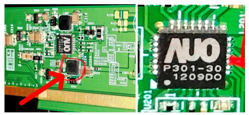
As you can see, the booster IC number is P301-30, the schematic of which is given below for ready reference:
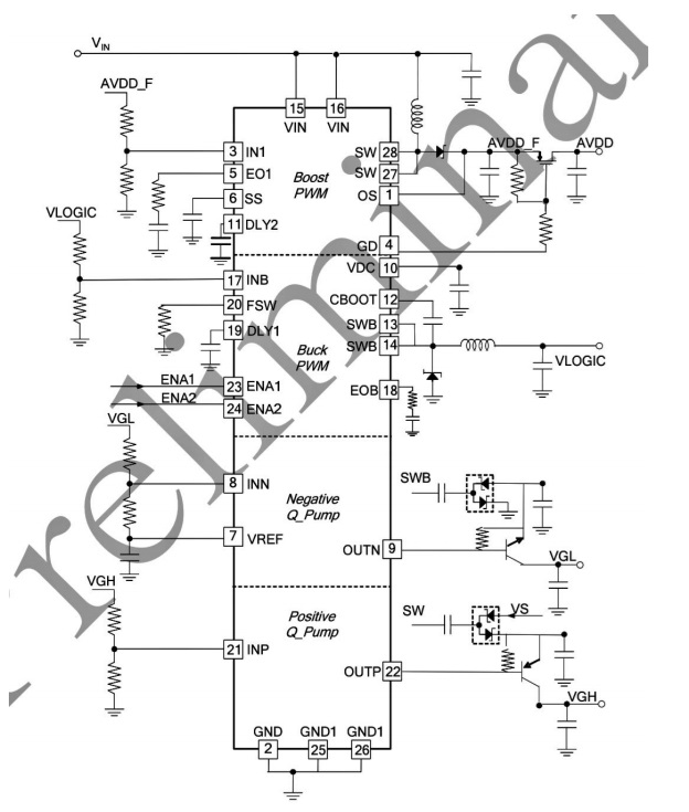
As you can notice, the 12V in goes to pins 15 & 16 to this IC, and builds up AVDD required from the coil and cap. The switching is done by pins 1, 27 & 28, rectified by a diode and smoothed by a cap and controlled by a Mosfet to generate AVDD, which can be clearly seen in the diagram. This IC also generates the VGL & VGH voltages for the panel.

Click here to check out Humphrey’s ebook on LED TV Panel Repair
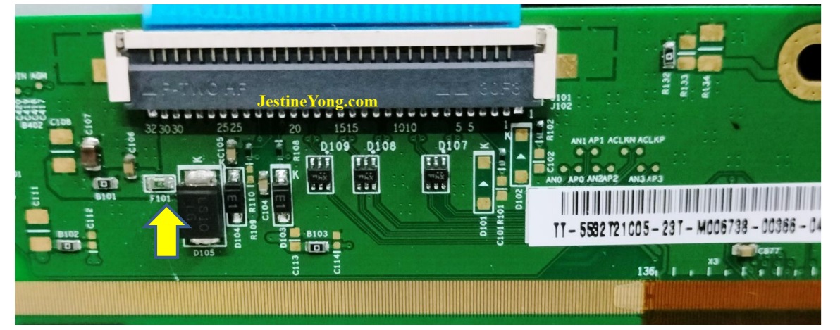
The next step was to check all the components in the scalar board, pictures of which are shared below for ready reference:
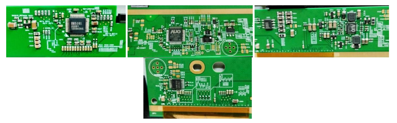
I combed the entire board for any direct short or leak of any SMD caps and did not find any. But one SMD three pin component marked as W5 was found short. The search in the web brought multiple results for W5 including Zener diodes and ICs! As three pins on the board were used, it could not be a Zener. This component was in the AVDD line which went to yet another slave IC before it went to the panel through the COF. So, my assumption was that it was a switching Mosfet used to supply AVDD to the slave IC subject to sense of ideal conditions. I hunted for a replacement of the Fuse, Coil and this component and I got an old scalar board from a techie friend. I removed the required components and replaced it, before which I checked the W5 in the checker, by soldering three legs to it:
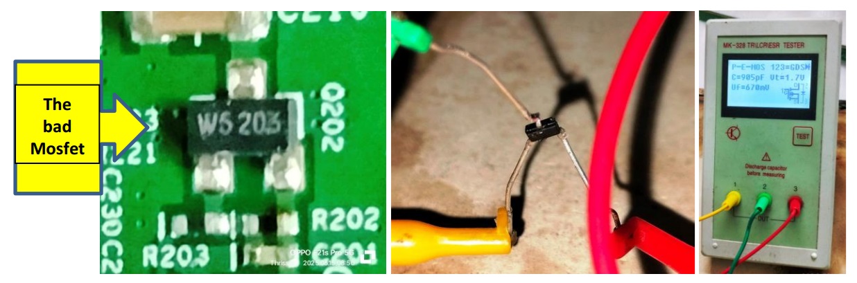
As you can see, it was indeed a P Channel Mosfet. Unfortunately, even after replacement of the components, the coil smoked indicating that the Booster IC itself was the culprit. I removed it and ordered for a new one. Rechecked all components for any damage and did not find any. My techie group friends advised me to go for a replacement of the scalar board as any defect in the other ICs, which cannot be easily detected can blow the new IC again. Anyhow, I got a new IC and replaced it. Replacing such a tiny SMD IC which has the heat sink pad underneath is extremely difficult. For removing itself, I had to scrape the bottom of the PCB where the IC was fit and apply heat from top and bottom abruptly alternating (480 degree with Air flow at 5 on a Kada 2018 D+). But I could take help from a techie friend, who came home and fixed it, as he was an expert in such jobs. But it was a disappointment as forecast by my friends! Again the voltage dropped! So, I spoke to another techie friend who was involved in panel bonding and replacements. He gave me an appointment and I carried the TV in my car along with yet another 43” Sony which required panel replacement. I had to wait for almost a day as the shop was thronged by technicians and hundreds of TVs were lying all around the five rooms-joined-together shop, which housed a laser machine and bonding machine.
I reached there by around 10.20AM and got the scalar board replacement work done by evening and by the time I could reach my home, it was around 6.30 PM! (I had to take a vegetarian meal from a nearby hotel! I always carry my medicines in my waist pouch for meeting such exigencies) I removed the TV from the car and fixed the back cover only on the next day morning. Then allowed the TV to run for several hours before informing the customer. As the TV was coming to me for the second time with power supply related problems, I insisted on checking the power supply outlets in the customer’s home and hence I carried the TV in my car along with a multimeter and minimum tools and went there. I checked the voltages in their house and found it to be normal 220V AC. Then made enquiries about how they were connecting the cables, its set top box and TV. They showed me a three pin three way adaptor, in which they plugged the mains cords of the TV and set top box. My hunch was correct! The two power pins were loose and I could see darkened contacts inside one of the pins. So, the contacts were intermittent and that is why they had repeated power failures! I have done such inspections elsewhere too. Anyhow, the TV with its set top box were installed directly to the wall plugs and I waited there for sufficient time before departing accepting a cup of coffee and snacks from our friend. Of-course, he paid my charges decently enough to cover all my expenses and make a small profit! Altogether it was a good work that had a pleasant and happy climax. Let us have a look at a picture of the TV (when it was being tested on my work table) before announcing that intense satisfaction was permitted inside its collection bag with a warm welcome:
P.S. Perhaps you would notice in the schematic of the IC that it had two enable pins (23&24). My assumption is that one enable input comes from the µController to switch the IC on and another as a feedback of AVDD supply to the slave IC/panel. The datasheet shows 23 as Step-up PWM Enable Pin (When ENA2 is High) with default high. Pin 24 was Step-down PWM with default high. Just thought of sharing this info for further discussion and guidance by experts in the forum!

This article was prepared for you by Parasuraman Subramanian from India. He is 76 years old and has more than 30 years’ experience in handling antique equipment like Valve Radio, Amps, Reel Tape Recorders and currently studying latest tech-classes conducted by Kerala State Electronics Technicians’ Association. He has done graduation in BBA degree, private diploma in Radio Engineering and retired as MD of a USA company. Presently working as Consultant to Hospital and other institutions.
Please give a support by clicking on the social buttons below. Your feedback on the post is welcome. Please leave it in the comments.
P.S-If you enjoyed reading this, click here to subscribe to my blog (free subscription). That way, you’ll never miss a post. You can also forward this website link to your friends and colleagues-thanks!
You may check on his previous article on Power Surge Blew 12V Adaptor And PS IC In LG Monitor Model W1643C
 (1)Dislikes
 (0)
(0)


