
This SONY Component System Model HCD-GNV99D Awaits Transplantation
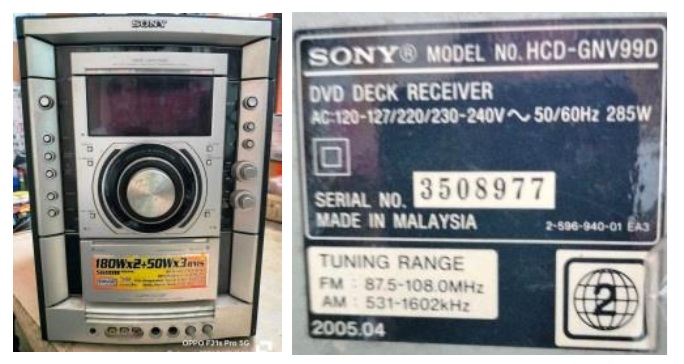
This set belonged to a techie involved in a different line of electronic work, who is a customer of my another techiefriend. It was brought to him with the complaint that display was not working, though the system responded to all commands and functions but worked with distorted sound. Though my friend asked me whether I could take up the work, as he himself was handling a different line, I could not accommodate him due to overload of work at my end. But I provided him the service manual and also gave him necessary guidance. Unfortunately, he could not do much especially due to hard of time, and left it there for many months.
Finally when the customer urged for getting the set back, he once again approached me and I had no other go except to yield to his request because of his closeness. I ventured so only because I could fetch its service manual from the web. When I powered the set, it was found dead without even an indication of power on LED. Probably the storage had made the condition worser. Anyhow, I opened and dismantled the set completely keeping it at my car porch verandah, as usual. Let us have a look of the insides:
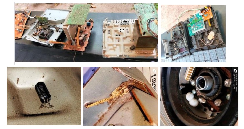
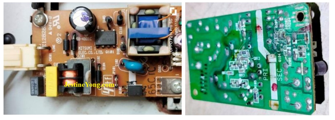
I happened to see an electrolytic capacitor lying loose under the bottom, eggs and skeleton of a gecko. After thorough cleaning of the inside, I reassembled the set on my work table. At this stage, the CD player unit and tape mechanism portion were not connected in order to focus and study the problems related display. Again powered on to see that the set was dead. Looking at the schematic, I could locate the problem to an SMPS Power Supply board which supplies 4V to the system for startup. It was in a bad shape with a lot of dry solders that had got hardened like rock. Following is a picture of the board before I completed the work:
I had a lot of difficulties in retouching the board, which had an important function. After cleaning the board once again, when I reconnected, the standby LED lit up and got released when the power on button was pressed, which indicated that the uController was ok. Then turned my attention to the front panel to study why the flourescent VFD, which was a SAMSUNG SSVD HNA-24LM01T not getting on. As the number of the IC on the board could not be read due to some dark coating on it, which could not be cleaned, I got it from the schematic and it was IC902 – MB90M407PF-G-145E1 (DISPLAY CONTROL, KEY CONTROL). I checked the voltage of filament and found it missing. On combing the board I observed that a zener diode was open and an SMD resistor was missing.
The fallen capacitor, the resoldering marks in the area where I was combing and also on the crystal of the uController showed signs of someone else trying to rectify the problem, as my techiefriend never did anything on the board, except changing the strained strip wire. I provided the zener diode and the resistor externally as I did not have stock of SMD type. After providing this circuit, the filament voltage showed 3.6V AC between the two pins at both ends. Then checked the voltages at pins of the display controller IC and found there were no abnormalities. Crystal oscillation was also ok. I removed the display as I noticed corrosion.
Let us have a look:
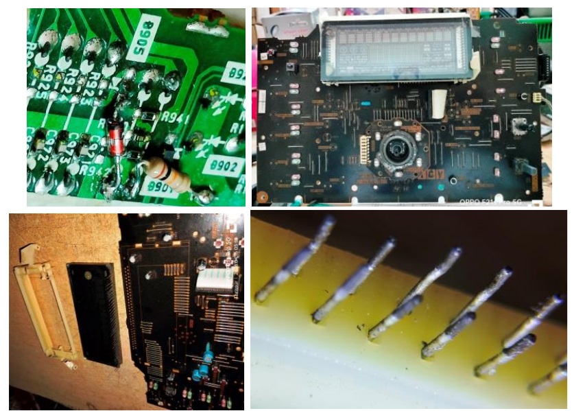
The first image is that of the bypass fitting of components. Second picture is that I took much later, after removing all the push to on buttons except on/off, reason for which will be explained later. Applied power after cleaning the legs properly and refitting the display. But the display was not getting on. All the voltages to be present in the Grids as well as Plates of the display were present as indicated in the schematic. So, the display IC was not getting on and the clock signal from the uController IC was starting but stopping, as there was no response (I mean, no hand shake). In all probability, the display IC would have conked off or software got corrupted when the VFD failed opening the zener.
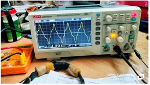
Evidently some power spike has caused this problem. I checked the spectrum signals at the respective pins and got the following result:
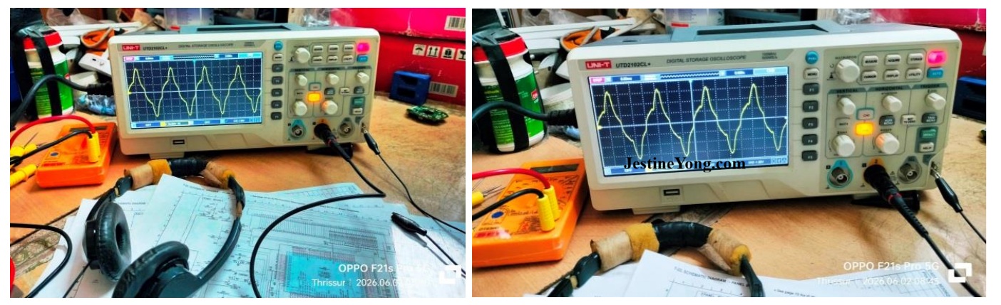
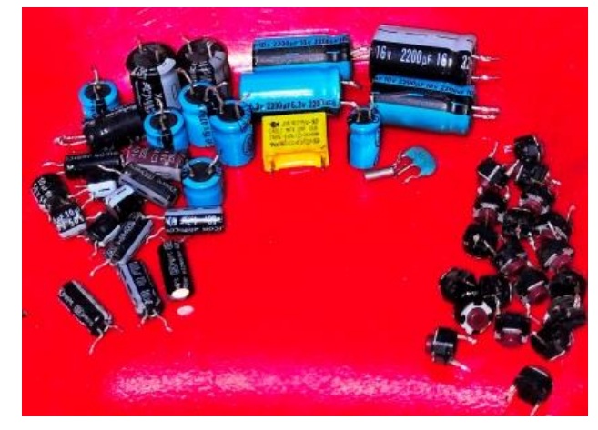
So, it was evident that all that is required from the Main IC was present. The next step was to ensure that all DC supplies were stable and pure. For that I replaced all the electrolytic capacitors on the front panel and around the uController. Removed all the push to on switches except the on/off as leakage in them would cause IC shutting down.
Except display button and on/off button, all others were connected to the IC.
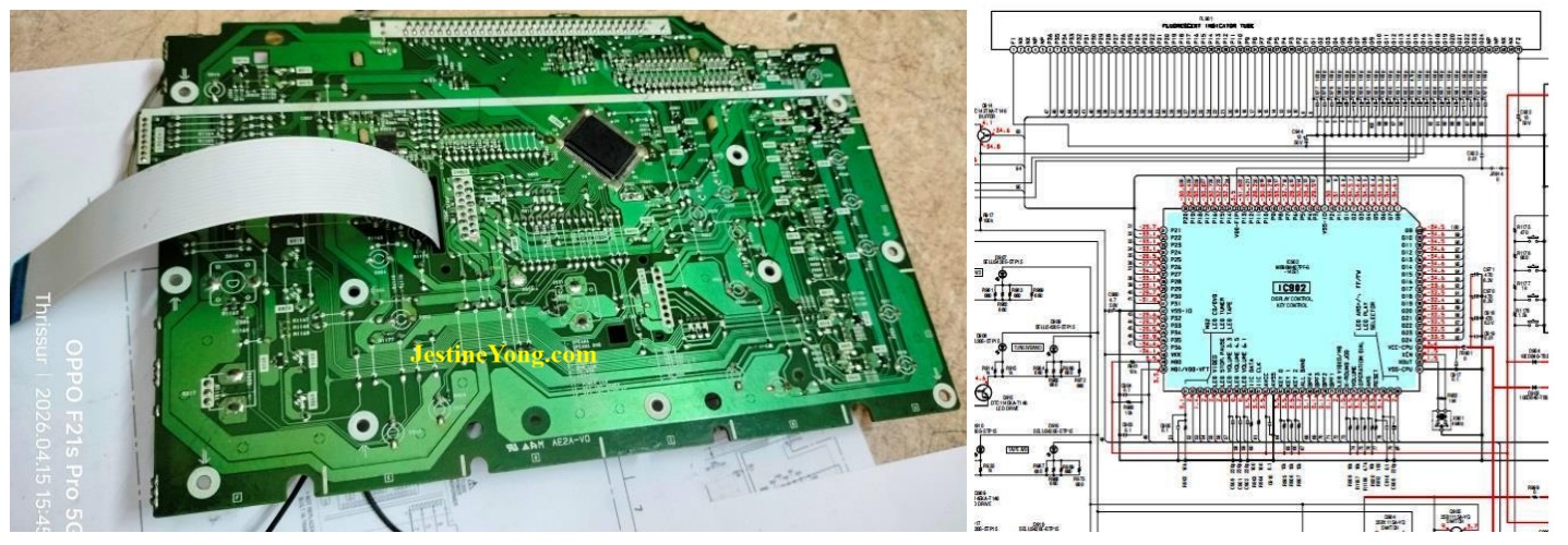
All attempts to obtain a replacement IC failed. I even tried getting a working panel board in vain. Since the customer mentioned that he would fetch a replacement board from abroad through his contacts there, the set was re-assembled and checked. It started up well with checking of all discs at the initial with the laser beam searching for a CD. The rotation was also ok. I forgot to mention that the original remote brought by the customer later on my request did not work and an equivalent RC unit brought also was same, though the IR was receiving the signals and they were reaching the input pin of the uController. My hunt for a compatible RC unit also ended up in vain. Since all the commands for function from the RC unit go directly to the uController, which was found to be working, a chance of getting a suitable one would resolve the issue. But display might have to be compromised. So, the set is hanging without knowing its destiny. If and when the display board is obtained or at-least the RC Unit is fetched, I can switch it on and try all functions with speakers connected to decide whether there are any more problems requiring a total restoration of the audio section.
Customer did not want the tape mechanism to be functional. He was planning to use it as a 5.1 speaker system for his TV and other audio devices. So, here is a case with only a partial satisfaction getting a reluctant entry into the collection bag! Well, the only solace was learning a lot and lot from analysing the schematic, working functions and other methods, which enriched my knowledge.

This article was prepared for you by Parasuraman Subramanian from India. He is 76 years old and has more than 30 years’ experience in handling antique equipment like Valve Radio, Amps, Reel Tape Recorders and currently studying latest tech-classes conducted by Kerala State Electronics Technicians’ Association. He has done graduation in BBA degree, private diploma in Radio Engineering and retired as MD of a USA company. Presently working as Consultant to Hospital and other institutions.
Please give a support by clicking on the social buttons below. Your feedback on the post is welcome. Please leave it in the comments.
P.S-If you enjoyed reading this, click here to subscribe to my blog (free subscription). That way, you’ll never miss a post. You can also forward this website link to your friends and colleagues-thanks!
You may check on his previous article on Source COF Found Short Between VGL & VGH In COOCAA LED TV Model 42S6CG
 (32)Dislikes
 (0)
(0)
12 Comments
Leave a Reply





Albert van Bemmelen
October 3, 2026 at 6:28 pm
About not having the original remote maybe this universal programmable remote from Superior-electronics.com helps? In its database there are many Sony HCD- type devices present. But not the exact gnv99d. However since the original remote according to Google's AI is the Sony RM-AMU001 maybe the available RM-AMU002, or the 2 other availbales AMU00x remote models works with this Sony audio set?
Parasuraman S
October 3, 2026 at 11:03 pm
The set was subsequently collected back by the customer, and I too got fed up working on it for days together, piling up my backlog. Many thanks for your expert comments and suggestions, dear Albert!
Yogesh Panchal
October 3, 2026 at 6:41 pm
Good Fix! Sir
When the device is fixed and works only partially for some reason, we also feel incomplete.
Parasuraman S
October 3, 2026 at 11:04 pm
Many thanks for your comments, dear Yogesh Bai!
Francisco Correia dos Santos
October 4, 2026 at 12:10 am
Tenho visto as publicações desse senhor, o que me chama atenção é quantidade de capacitores que ele troca. Imagino que ele tenha trauma com capacitor, ou tem uma fabrica do mesmo. Tenho mas de 40 anos de bancada!
========================
I’ve been seeing this gentleman’s posts, and what strikes me is the sheer number of capacitors he replaces. I imagine he’s traumatized by capacitors—or perhaps he owns a factory that makes them. I’ve got over 40 years of bench experience!
Parasuraman S
October 4, 2026 at 11:01 pm
Yes, every set when it is quite old and unused, the electrolytic capacitors are the first set of components that wear out and cause every trouble. So, first and foremost is stabilize the filters and signal paths and that is why I undertake such painstaking laborious work. The utmost satisfaction when it works perfectly after all these toils, overtakes such fatigues. Many thanks for your comments.
Imoudu.O
October 4, 2026 at 2:22 am
This's must have been a straining job I guess, but you still successfully wake it up partially for now...it's an experience!!
Parasuraman S
October 4, 2026 at 11:01 pm
Many thanks for your comments, dear Imoudu.
Mark J
October 4, 2026 at 3:18 am
Parasuraman you still did a great job even though you feel incomplete. Thank you for sharing.
Parasuraman S
October 4, 2026 at 11:02 pm
Many thanks, dear Mark!
MP
October 6, 2026 at 3:58 pm
Your ideally perfect explanation of the crystal-uController operation relation moves me nearer to understanding their often coupling idea. Thanks.
Parasuraman S
October 7, 2026 at 7:46 pm
Glad to know it was useful. Many thanks for sharing your comments!