
Very Complex Floppy Disk Controller Board Finally Fixed After A Long Time Of Investigation!
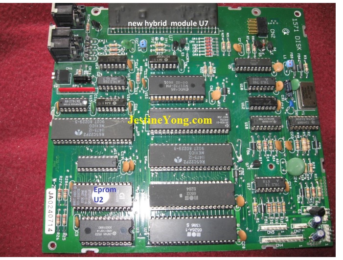
This repair is about fixing above shown defect complex Commodore 1571Floppy Drive Controller (FDC) board. (Special attention to the labelled Eprom U2 and Hybrid module U7)
It was just caused by accidentally placing back 2 false marked connectors back wrong onto the pin rows of CN1 and CN3. All connectors were placed back in line with connector marking pin1 plugged onto board pin row 1 which was only right for connectors CN4, CN5 and CN7, but completely wrong for CN1 and CN3. Which I only found out later which immediately had destroyed my no longer working Commodore FDC 1571 drive. Which come to think of it is a rather foolish thing that Commodore could have prevented by simply making it impossible to plug the connectors the wrong way on. Afterwards I started placing all ICs onto sockets to make it possible to test them off-board. This tedious work all started at least about 6 months ago in expecting to solve the error this way soon. Already a couple of years ago on 5 may 2018 I had ordered a used but working 1571 replacement board on eBay. Which I now used to examine and compare the ICs on my bad board with.
The error my bad 1571 board gave before it was fixed was a twice blinking green led in about every new second. Plus a constantly running drive motor. Of course I had searched all over the internet for clues to solve my twice green blinking led with running motor problem but could not find anything that pointed me in the right direction to solve my defect 1571 board.
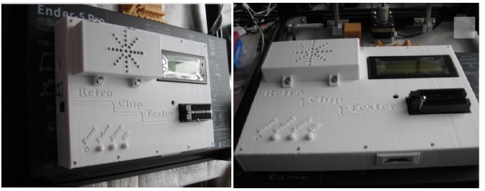
Normally with a good board the green led and the motor only briefly go on at power up. By checking all socketed ICs on my bad FDC board I already found a bad 6502 CPU of which databus pin D6 was defect. And also a bad VIA or CIA. I checked some of the ICs with my already new finished made RCT tester from 8bitmuseum.de. And the CPU with another made cheap 6502 NOP tester board that also is sold by Stephan from 8bitmuseum. Next photos show my Retro Chip Tester (RCT) ready built into a in about 41 hours 3D printed exact fitting case. Even the 4 push buttons for this case were perfectly 3D printed! This case can be found on https://www.thingiverse.com/thing:5102850. And proof of my 3D printed Make on: https://www.thingiverse.com/thing:5102850/makes
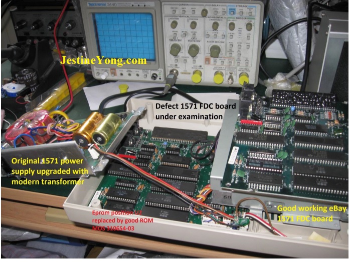
And in the meantime I also had ordered a special new ready built Chip_Tester_Pro from Evie Salomon in the USA that already can test almost all special Commodore C64/128, Amiga, ZX Spectrum, Atari, plus many other ICs! Including complex digital Floppy controller chips like the WD 1771 and 1772 which also is used on the 1571 board! Next photo shows the test bench setup I used to measure if my new received Hybrid U7 module on my defect board was working by comparing it with my good working board and its Hybrid module.
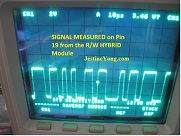
Of course I examined test pins TP 1 and TP 2 (pin 17 and 18) and pin 19 DATA of the 30 pin R/W Hybrid module U7 of Commodore MOS chip 251853-01 or M36A2U57. Because at that time I thought everything was checked and replaced except this module that sadly can’t be easily tested. And I already even had replaced the 3 pin voltage detector U21 PST520D by a new PST520C type detector which only marginally differ in voltage. (I could not find the originally used 520D type detector). But that made no positive change. So the Hybrid module seemed the only left factor causing the problem. These 30 pin modules or these boards are very hard to find especially brand new modules but luckily seller comp preservation on eCrater still sells these new modules. Within only several weeks he was able to ship one to me! However afterwards measuring the Hybrid module signals on pin 17 to 19 of both good and bad 1571 board revealed the identical working square wave signal on Data pin 19. As next scope screen copy clearly shows.
Replacing the complex undocumented Hybrid U7 module therefore likely was not necessary because it measured exactly the same on both 1571 FDC boards. But at first the new module looked different component-wise under its coating compared to my original Hybrid module. But the new module afterwards worked exactly like my original module does. And this was tested by loading the game Krakout II by connecting my 1571 to my C128D set as drive devicenumber 11, which worked splendidly on my 5.25 inch Floppy disk after about +30 years! Following photos also show both different looking but identical working 30 pins R/W Hybrid modules.


Also shown next is the fantastic Chip Tester Pro I needed to quickly test my +30 year old ‘retro’ ICs. Without such a Chip tester it is very hard to check if complex VIAs, CIAs, GATE Arrays, FDC controllers, CPUs or RAMs are okay!
With the Chip Tester Pro from Evie we also can easily copy the U2 Commodore ROM and save the bin file to the integrated Micro SD card. And this also is the easy way to upgrade when Evie launches another free upgrade download. I do not think there is a similar ready built tester for the affordable price asked for this unique designed piece of hardware and firmware why I bought it!
We just place the frequently on Evie’s website shared new free upgrade file onto the Micro SD card. And insert the Micro SD Card back into the upto 48 pins supporting tester and switch the Chip tester on by providing 5V on the USB port. And when we want to test ICs we just follow the LCD messages on how we need to wire the plus and min wires to power our with the digital-select-potmeter selected chip under test. Which is shown on the second Chip Tester Pro photo that follows.
Still searching for the culprit I started checking the only chip I had not yet swapped with the chip on my good board. Which was the MOS chip on my good working 1571 board that I swapped with my 27C265 Eprom on my bad board. And Eureka! That immediately solved my led blinking and motor running problem!
With Evie Salomon’s fantastic Chip Tester Pro we easily can test practically all ICs on the Commodore 1571 board. Except for the special 30 pins Hybrid chip U7, and IC U5 which are not (yet) supported. Including easily copying the ROM chip U2 MOS 310654-03 chip selected as Eprom27C256 chip to the internal micro SD card. Establishing that U5 was okay was easy by simply swapping it with the U5 on my good 1571 board. U5 is connected to pin 19 of the Hybrid module. Next circuit shows the complexity of this special Commodore designed intelligent FDC board (because this FDC controller uses its own RAM/ROM/IO plus 65xx CPU !). Several 1571 document downloads can be found on:
http://www.zimmers.net/anonftp/pub/cbm/schematics/drives/new/1571/index.html
More info on the RCT tester and the Chip Tester Pro can be found on these internet links:
* https://8bit-museum.de/sonstiges/hardware-projekte/hardware-projekte-chip-tester-english/
* http://backbit.io/downloads/Firmware/ChipTester/Pro/
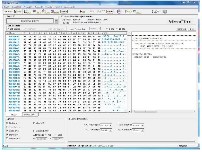
Because the original Commodore Eprom U2 no longer was working, I used my TL866II to program a new working 27c256 Eprom with the data file read from my good working Commodore U2 ROM. And I also first cleared the data in my Eprom with my UV Eprom Eraser light. The screencopies of the successful TL866II reading and Eprom programming results are also shown in pictures that follow.

Below photo shows the fantastic Chip Tester Pro from Evie Salomon with the micro SD card insert

Next photos show the set 27256 selection to read and copy the original Commodore version -03 U2 ROM. Plus in the photo on the right the power lines + (red) to socket connection pin 48 and – (blue) to pin 14 of the test socket to power up the ROM under test.

Next screencopy shows that the Commodore U2 ROM also was successfully read with my TL866II. The content of the good U2 (v.1985) ROM was used to program a new 27C256 Eprom with. But before reading the original Commodore ROM we however first will get a message from the programmer complaining that the TL866-II (or the Xgecu Pro) can’t make a good connection (the built-in chip contact test) with pin 1 of that chip. But we can completely ignore that error message because that pin is only important if it was the Vpp programming voltage pin of a 27C256 Eeprom.
Following screencopy shows the successfully programmed new 27c256 U2 Eprom copy.


Previous photo showed the already good working on eBay in 2018 bought replacement board that are very hard to find these days. And prices asked now often go through the roof!
To sum up this repair, The recently on 14 April 2022 from trusted seller comppreservation new bought Commodore 251853-01 Hybrid R/W, BRAND NEW, 1541B 1551 1570 1571 Floppy Drive: 1 x $24.95 = $24.95 Hybrid chip probably was a different manufactured version Hybrid chip that looked different under its coating component-wise compared to my original Hybrid module as both photos showed but also worked fine!
And probably all my previously invain checked Hybrids are still fine. Previously only my processor and probably one or two of the MOS (VIA.CIA) chips including the last culprit Eprom U2 apparently were defect!
Which all was caused by the fact that both power connectors CN1 and CN3 are marked wrong with pin 1 on both connectors. So keep in mind that both connector plugs have to be connected plugged-in 180 degrees turned!
Also know that zenerdiode CR11 attached to Q5 in the Commodore 1571 FDC schematic is not a 3.3V zener although that is what it says on the diode and in the circuit, but in fact all these zeners were in reality 2.7V zeners when measured out-circuit with the Peak Atlas DCA75 Pro semiconductor tester.
Following last photo shows Q5 onto a 2.7V zener (also marked as being a 3.3V zener) with on its right the drive heads connector and on its left a swaptested 20 pins U5 MOS 251829-01 good Commodore chip. Which Evie’s Chip tester Pro and neither Stephan’s RCT tester are able to test (yet).

Now my original complex FDC board is completely repaired and tested working fine with over 30 year old 5.25 inch floppies. (Tested perfectly working fine with Krakout II loaded into my C128D)!
Lesson learned here: Never think .. that part or component is not the problem here… and no need to check that!! Because a probably already about 37 year old EP(ROM) obviously was the only culprit left here after the other bad chips already were checked and replaced.
I knew I had not yet checked this Eprom by also swapping this U2 chip with the good U2 ROM on my good board. I previously only had read it with my TL866-II programmer to see if it still was accessible which it was. But obviously that was not enough to confirm it was 100% okay.
And when I finally found the final last existing culprit, being this bad Eprom U2, I also noticed that without inserted U2 (EP)ROM the green led constantly stays on.
Final note: The RCT tester can only be built with the 2 boards that can be ordered from Stephan from 8bitmuseum.de. After that all tester components need to be bought from an electronic shop of choice to assemble this affordable tester. Stephan shares all gerber files, instruction manuals and the component bom list with any buyer of his boards. Firmware upgrades are free for registered buyers.
Evie’s special very unique Commodore compatible Chip Tester Pro is already completely built. And frequently shared new upgrades are free and easily done by simply saving the new firmware on the inserted micro SD card. Evie also makes and sells several other Commodore and other personal computer related electronic devices.

Albert van Bemmelen, Weert, The Netherlands
Please give a support by clicking on the social buttons below. Your feedback on the post is welcome. Please leave it in the comments.
P.S- If you enjoyed reading this, click here to subscribe to my blog (free subscription). That way, you’ll never miss a post. You can also forward this website link to your friends and colleagues-thanks!
Note: You can read his previous article on Make A Very Cheap Power Adapter Of Defect Electric Tooth Brush Charger
 (45)Dislikes
 (0)
(0)
14 Comments
Leave a Reply


Paris Azis
May 15, 2022 at 5:41 pm
Excellent job, Albert! Thanks for sharing it!
Albert van Bemmelen
May 15, 2022 at 8:45 pm
Thanks Paris. I am very happy to finally have restored my original now second spare FDC board after quite a few months of soldering and testing......
One thing I like to add to this repair worth mentioning is that Evi's Chip Tester Pro also can test chips IN-CIRCUIT. Instead of the standard out-of-circuit chip testing method she calls LOOSE MODE testing. But that is not always a success because of databus and addressbus conflicts that may occur when more chips use the same data I/O bus and power lines. And is also why the Chip Tester uses a rather large power supply protection fuse internally (2A) when more chips start to draw current at the same time in-circuit. Which is something I also had noticed in other repairs I did where the chip, like an Eprom or Sram, I tried to read or copy at the same time activated the on board connected cpu through its power lines.
Hence why the Loose Mode or out-circuit test method always gives the best results. But that took much more time for all the high quality sockets that needed to be installed after every single chip was desoldered and afterwards placed back after the chip testing.
Parasuraman S
May 15, 2022 at 6:58 pm
Too complex to comprehend and most of it went above my head! But excellent professional work! Hat's off!
Albert van Bemmelen
May 16, 2022 at 1:45 am
Don't sell yourself short dear Parasuraman. Because if even I can do it, I'm sure so can you! (Lol)
And you've done so many timeconsuming repairs I wouldn't even think of doing!
Parasuraman S
May 18, 2022 at 11:58 am
Many thanks!
Anwar Shiekh
May 15, 2022 at 10:11 pm
Beyond impressive, I tend to just stick with the easy fixes.
Lynn Blakely
May 15, 2022 at 11:12 pm
Dear Sir Albert: Wow that is an amazing repair, with excellent documentation.Thanks for sharing.I owned a C-64 and a C-128, I wish that I had not sold them as there were some excellent Math training programs from a company I don't remember.
Albert van Bemmelen
May 16, 2022 at 1:03 pm
What is stopping you from buying another new or used C64 or C64 clone computer and re-install that nice Math program? The newest C64 remake will come soon too after its previous C64 mini release was sold! Maybe something that will be interesting enough to buy one of those?
Yogesh Panchal
May 16, 2022 at 1:02 am
Albert,
Good fix!
Still using Commodore 1571Floppy Drive???? for what purpose???
Albert van Bemmelen
May 16, 2022 at 12:40 pm
After owning a VIC 20 and lateron a Commodore C64 my computer collection grew. I especially like Commodore when I also started fixing defect second hand C64 computers, but also ZX Spectrum and other digital electronic devices. I still have a collection of those now retro older personal computers including software. Including Amiga and Xbox machines too. One of the first TTL IC testers I made was for the C64/128. Some unique software programs on those first colour personal computers never found their equal substitute on other computers! All my computers work pefectly even after +30 years! And often are also upgraded to todays newest hardware upgrades we can find. Like floppy emulators that use SD card or USB memory sticks.
Waleed Rishmawi
May 16, 2022 at 1:39 pm
not my area of experience but surely it was a lot of information to take in. thanks for sharing though. have a blessed day
Albert van Bemmelen
May 16, 2022 at 9:27 pm
Addendum: In case anyone also needs to make and program a new Eprom U2 rom for his FDC 1571 he probably is advised to use the version 05 bin file because the ROM and Eprom version 03 I used is still known for having a small bug. A problem that was solved in U2 ROM version 05. Here is the link to that file:
http://www.zimmers.net/anonftp/pub/cbm/firmware/drives/new/1571/1571-rom.310654-05.bin
It corrects the bug of 310654-03 that moves the R/W head between each sector when writing on the disk's top side.
Albert van Bemmelen
May 19, 2022 at 2:46 am
Note: Apparently the very mysterious U7 Hybrid module in Commodore's 1571 Floppydrive was maybe also used in Akai VCR videorecorders? Which is unexpected and also not confirmed. As said documentation on this 30 pins module is so good as non-existing and also Akai and/or the chip manufacturer do not have any information about this hybrid chip sadly. Anyway... here is a link that shows the Akai hardware connection:
https://www.hqelektronika.hu/hu/vcr-hybrid-ic-akai--30p-h36a2u57
Albert van Bemmelen
May 19, 2022 at 2:53 am
Note2: Later on Commodore apparently used a Sony CX20185 chip in its newer Commodore Floppydrive units. Some sellers sell this chip as being a dolby audio chip which could be wrong if it is originally in fact a Floppydrive head amplifier.