
Yet Another Antique Set, SONY L7 Cassette Deck Model EL7 Restored
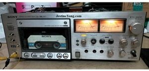

This was brought to me by a recently added regular customer and was one among the many antique sets that he loves to collect and maintain. The set had gone to another technician a few years back, but taken back as he could not do anything on it. It was lying in one neglected corner until he found me, another crazy guy on the other end who goes all out to restore such sets. First of all I was amazed to see that there existed such a set, as I had never seen one like this before. The L7 cassette was the next to come after the reel tape recorders just before the compact cassette recorders came to the market. The tape cassette looked like olden days’ VCR cassette, but length was less.

I opened the set to see a lot of dust well settled on all the crammed looking inter connecting wires, boards and parts.
Though used a blower, only loose dust went off and those which camped on boards and wires refused to budge.
Anyhow, I decided to replace the broken belt for which I removed the motor and capstan wheel and was surprised to see that a piece of flat belt was pasted on the capstan and there were thick coatings of this on the pulley of the motor too. Let us have a look at these:

The pasting done on the capstan wheel was to tighten the loose belt and was a very crude way of doing it. The wheel would wobble and it would cause flutter when a tape is played. The running of the capstan wheel should be very smooth and shake free. I scraped these extra fancy fittings and cleaned the pulley and capstan wheel and replaced the belt with the correct width and size. Then applied power and played a cassette brought by the customer. The motor was running, take up wheel was running, but the pinch roller did not get engaged to the capstan wheel. Then I knew that there were more problems in the set than envisaged. I downloaded the service manual of this set and studied the circuit diagram very well. There were four solenoids at the back of the tape mechanism; one for applying the brake, one for pushing the tape to capstan wheel and engage the pinch roller pressed on it, one for eject and one for engaging wheels for FF & REW actions. Let us have a look at this portion of the diagram:

Page 12 gave description of the functions of this portion with clear details of how each operates and what happens when a key was pressed. But the main hurdle was doing the checking on this board which was fixed on one side with hinges for tilting it to a certain extent. The boards were indeed marked with important component numbers, like transistors and diodes with base/collector/markings. But unless we have the board accessible from both sides, trouble shooting would be extremely difficult. Anyhow, I checked what I could in this way and found many electrolytic capacitors out of ESR and range. With a lot of difficulty, I removed them one by one and just sharing the readings of a few to know the conditions found:

I replaced each and every one of them as every cap was out. Then did a dry solder patch up on the board, which was easy, as the bottom of the PCB was exposed. You can see the control board with partial power supply fixed on the right extreme side near the mechanism in one of the pictures given earlier. (I am avoiding use of ‘cum’ in order not to irritate one of the experts who is regular in this forum! (LOL). After this laborious and time consuming work, the problem could not get solved. I checked the voltages at each and every transistor bases, collectors and emitters and also checked them using my analogue multimeter in X1 mode. Checked all diodes too, whichever were marked from behind. There were many that could not be accessed. I even removed a few transistors to check it in my tester. I did not find anything wrong.
After spending several hours trying to figure out what could be wrong, by working on the set on different days whenever I got a gap, I got vexed and decided to take out this board, by cutting the wires and extending it like I have done in a few sets before. The wires were clearly marked with different colours and stripes. There were a few connectors too. The schematic was helpful to certain extent, but did not contain colour codes. What I did was cutting and leaving a portion on the board so that when I reconnect, I know which wire should go where. It was like a barber doing some hair styling! (LOL) I was careful to tape the wires together as a bunch to identify its target/source.

If we do not have the board accessible easily from both sides, we cannot check the values of the resistors and other components properly. That’s why I resorted to this cumbersome method as a part of ‘do or die’ attempt. Of-course, the customer had given me a free hand and asked me to do whatever deemed necessary. The next step was to attach extension wires for which I always used male to male, female to female or male to female inter connecting colored wires which were readily available in the market. These are called relimate connecting wires with housings at both ends. I removed the housings for a proper inter-connection, as I intended to solder them and provide a heat shrink sleeve as a protection. In order to connect the wires, I crimped female sockets on each and every cut wire on both sides. Inserted the interconnecting wires choosing appropriate matching colors. Wherever white wires with different colour stripes were used, I matched the colour of the stripe. In order to enable tilting the board upside down, I selected which are the connectors that needed extension and did such an extension work on that too. Let us have a look at the work in progress:

The last picture above is after finishing the work of inter connections ensuring that all joints were well covered with heat shrink sleeves for which I used my blower with controlled heat and air flow not to cause damages to the other parts.
Each and every connection was made after double checking and making sure of it and remembering to insert the heat shrink sleeve before attaching. Many times we tend to forget this and reopen the connection and I was careful not to commit that mistake. After all these works were over, I rechecked the connections and inserted the connectors which I had marked with the numbers to the appropriate places. But, unfortunately, the set was in the same condition. But this time, I could check both sides of the board. I studied the operation carefully and checked voltages while operating the set. The solenoid would work initially only at a voltage of around 40 and remain pulled at around 15V. Only the initial pulling required this high voltage. The circuit was designed in such a way that a transistor (Q718) will turn on when a pulse was received to its base, upon which (C713) 4.7uF/25V capacitor would get discharged, the other end of which was connected to yet another transistor (Q727), which had positive bias. So a negative pulse would go to its base and the transistor will go off, upon which two transistors (Q728 & Q729) holding 40V on its collector will get on and pass it on to the solenoid. By this time, the C713 capacitor would get charged and switch off the Q727, which will switch off Q728 & Q729. The company has designed like this to avoid overheating of the Solenoids and I really appreciated it!
Coming back to our problem, I checked the resistors that go to the base of Q727 (R771 & R712 – 8.2K & 3.3K). These were ok. But this kick voltage was not taking place, even though the discharge of the capacitor was taking place when checked. So, I suspected Q727, which was 2SC945. I removed it and checked and found it to be perfect. But not to take a chance, I replaced it as transistors which show ok could fail on load. Let us have a look at the circuit diagram and the explanation of this given by the company:

What I wrote above was what I understood from their descriptions without looking at the service manual or descriptions! I grasped the function and transcribed it into words for the readers to know.
When I applied power and operated the play button, the solenoid worked and I found that the 40V kick circuit was working well. But the solenoid holding transistor Q713, 2SC1124 was getting heated up and I replaced it with MJ13003 by connecting the B, C & E to the correct positions. I provided a sleeve to the collector as it was crossing over emitter.
Then played A & B sides of the two cassettes several times and found these to be working perfectly fine. But while rewinding one cassette, the tape got cut. So I opened the cassette and rejoined the cut tapes ensuring that the sides joined are facing the correct way. The method is to keep one side of the tape on the table, apply a drop of superglue and quickly place the other end on top it in perfect alignment and allow it to bond very well. Look at the following pictures which I think would be a rare collection:

It indeed cuts a very tiny portion of the recording, but it won’t matter much as it passes at a speed under the head. The cassette case has two springs inside the two protectors on both ends and we have to ensure that these are engaged properly while putting everything back. The tape worked well after this tie up!

Mission accomplished and bulgy satisfaction got sucked by the collection bag!
Like I mentioned in the first paragraph, am I not a crazy guy to do such crazy things for a repair? But I love to be known as one! The removed caps and other parts were packed and set was moved for delivery to the customer, putting a curtain to this repair story!


This article was prepared for you by Parasuraman Subramanian from India. He is 74 years old and has more than 30 years’ experience in handling antique equipment like Valve Radio, Amps, Reel Tape Recorders and currently studying latest tech-classes conducted by Kerala State Electronics Technicians’ Association. He has done graduation in BBA degree, private diploma in Radio Engineering and retired as MD of a USA company. Presently working as Consultant to Hospital and other institutions.
Please give a support by clicking on the social buttons below. Your feedback on the post is welcome. Please leave it in the comments.
P.S-If you enjoyed reading this, click here to subscribe to my blog (free subscription). That way, you’ll never miss a post. You can also forward this website link to your friends and colleagues-thanks!
You may check on his previous article on Failed Cases Of Two SONY LED TVs
 (32)Dislikes
 (1)
(1)
12 Comments
Leave a Reply


Ajay Kumar
September 28, 2025 at 6:36 pm
Such a laborious work on a vintage deck ! You do have a lot of patience and perseverance I do hope to meet you one day sir, while passing through Palakkad! Thank you for the informative article.
Parasuraman S
September 28, 2025 at 7:16 pm
You are most welcome! Many thanks for your encouraging involved comments!
Waleed Rishmawi
September 28, 2025 at 6:50 pm
that is alot of work for this old piece but I hope it was worth the time and effort. I am know you were happy about replacing the caps..LOL. I enjoyed your detailed article and I hope the customer paid you enough for the long repair job and parts replaced. thanks for sharing and have a blessed day
Parasuraman S
September 28, 2025 at 7:17 pm
Yes, the customer generously reciprocated! Many thanks, dear friend, for your continued support!
Albert van Bemmelen
September 28, 2025 at 8:36 pm
These repairs do not come easy seeing they were all but service-friendly (after reading about that 3 letter word you still mentioned!- lol).
Sony in the past was well known for using solenoids in Betamax recorders too.
I still have an old C5 toploader and a much newer SL-33EC VCR, but the first I never had used again after it once had practically 'attacked' one of my old Betamax tapes. I managed to fix that Betamax tape by cutting the partially wrinkled tape and glue both ends together afterwards.
One day (in about a year or so when I have more time) I still hope to successfully digitize a few old tapes with family videorecordings on them. Hoping that at least the Betamax SL-33EC VCR still will be working fine then.
And the old C5 probably needs a new rubber belt and a complete checkup before I dare to use it again.
Parasuraman S
September 28, 2025 at 11:07 pm
Thanks for your expert comments and sharing your own similar experiences. I look forward to your article on that VCR as and when you feel like restoring it! All the best for your digitalization plans.
Mark J
September 29, 2025 at 12:13 am
Parasuraman I always enjoy your Cassette Deck repair articles. Once again thank you for sharing.
Parasuraman S
September 29, 2025 at 3:33 pm
Many thanks, dear Mark! May God bless you!
AdamS
September 29, 2025 at 4:13 pm
Excellent repair Parasuraman and very surprising to see another Sony Elcaset deck out there in the wild. They are very rare things and highly collectable.
Parasuraman S
September 30, 2025 at 2:42 pm
Yes, very rare indeed! Many thanks for the time you are spending to write your comments here!
Muykit
October 1, 2025 at 8:20 am
What an outstanding authorship uniqueness that blends well with nicely outlined technical skills. The cassette player stretched repair exercise is an undertaking that only a few technicians in the know could handle with relave ease, 25 or thereabout years ago. But now, in the course of such a repair, most technicians will most certainly be met with the unfortunate challenge of spare parts scarcity. Thats quite a snag. Cassette players were a treasure to behold. Most new employees had one by the end of the third month salary. I have fond memories of a Hi-Fi music system whose lovely sound quality even some modern music players cannot outdo. It, as music played could be tuned to sound as though it was in another room when it actually was right at your feet. Its TWITTER sounded like it was on every nerve in my head, and the bass' every thumping seemed to be gently bumping on my abdominal organs. Which got me carried away by fantacy. A little later as fate had it, Hi-Fis disappeared and woofers took over.
Parasuraman S
October 2, 2025 at 9:12 am
Very true! Innovations and improvements done have compromised quality of enjoyment! The 'wide' option in compact sets was a good and pleasing feature in those days. Many thanks for your involved comments and inputs and sharing your experiences.